

Protecting method for sudden drop of electric and electronic equipment with medium or high electric power
A technology of power electronics and power failure protection, which is applied in the direction of emergency protection circuit devices, electrical components, output power conversion devices, etc., can solve problems such as power grid power failure, and achieve the effects of reliable operation, low cost and small size
- Summary
- Abstract
- Description
- Claims
- Application Information
AI Technical Summary
Problems solved by technology
Method used
Image

Examples
Embodiment
[0024] Embodiment: A sudden power failure protection method for medium and high voltage power electronic equipment
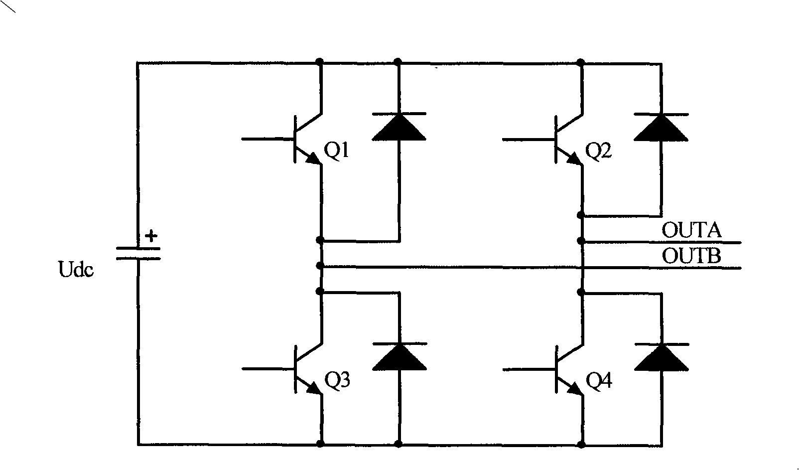
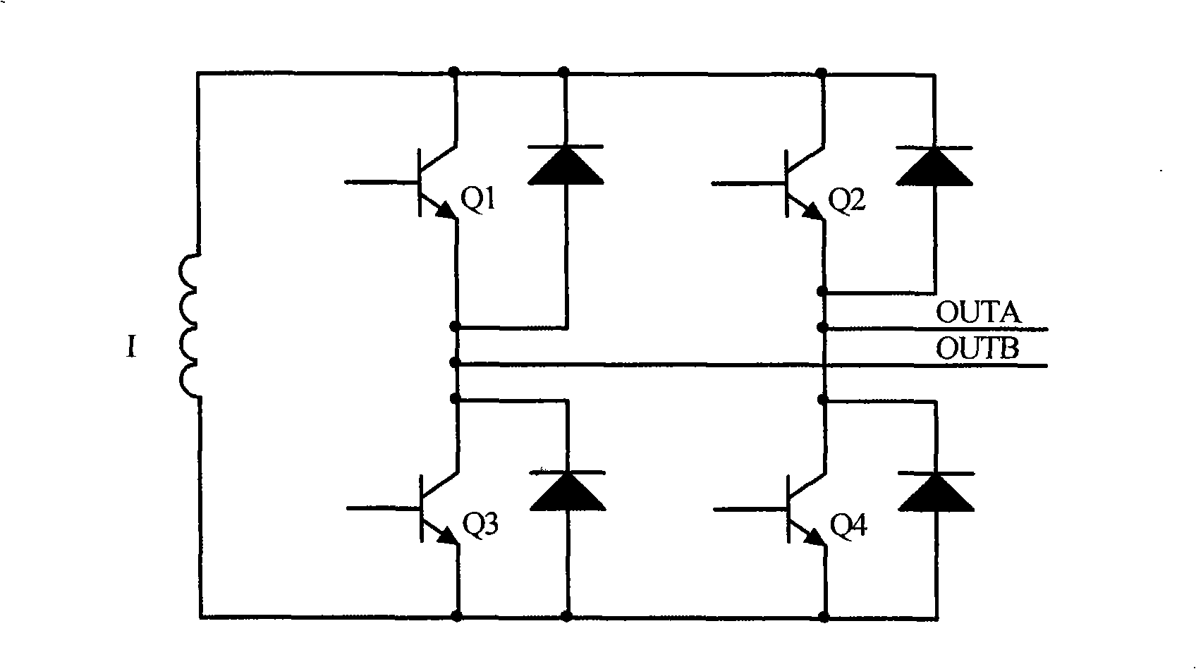
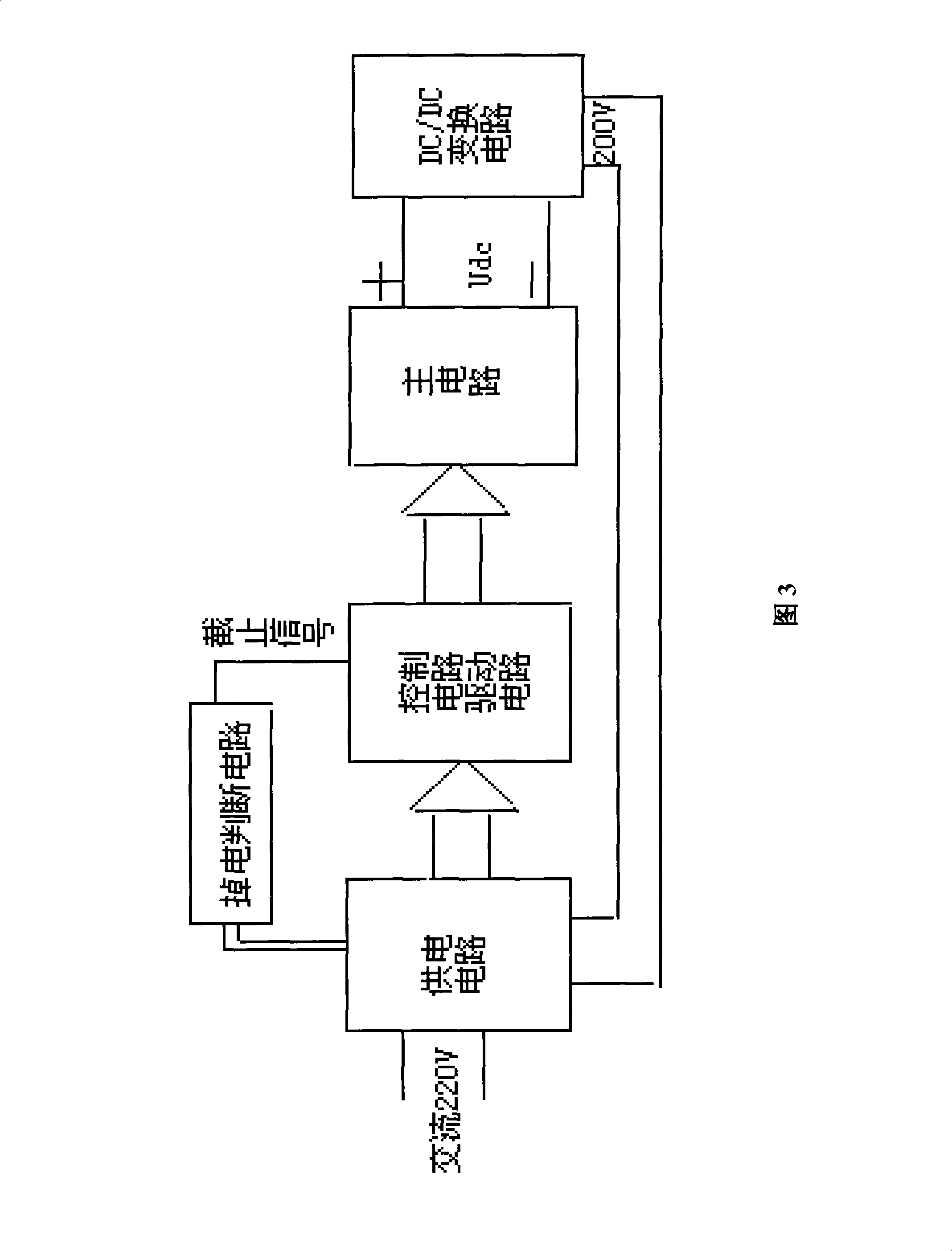
[0025] As shown in Figure 3, for medium and high voltage power electronic equipment such as voltage-type inverters, the DC power supply between the DC side of the inverter (that is, the output Udc of the main circuit in Figure 3) and the control circuit and drive circuit in the inverter A single-ended flyback voltage feedback circuit is added between the terminals (that is, the power supply circuit in Figure 3), and the single-ended flyback voltage feedback circuit is a DC / DC conversion circuit, so as to use the first capacitor ( refer to figure 1 In the capacitor), when the power grid suddenly loses power, the power on the DC side is fed back to the DC power supply end of the control circuit and the drive circuit. At the same time, a power-down protection judging circuit is added between the AC side of the inverter and the drive circuit of the inverter, and a ...
PUM
 Abstract
Description
Claims
Application Information