Retina cell microscopic imaging system capable of executing demixing scan

A retinal cell, layered scanning technology, applied in the field of retinal cell microscopic imaging systems, can solve problems such as difficulties, inability to layer imaging, and achieve the effect of obvious effect and simple structure

Active Publication Date: 2008-10-29
江阴龙跃信息科技有限公司 +1
View PDF4 Cites 6 Cited by
  • Summary
  • Abstract
  • Description
  • Claims
  • Application Information

AI Technical Summary

Problems solved by technology

For this reason, if the retinal cell microscopic imaging system cannot image in layers, each layer of cells will be imaged on the imaging surface at the same t

Method used


Image

  • Retina cell microscopic imaging system capable of executing demixing scan

Examples


Embodiment

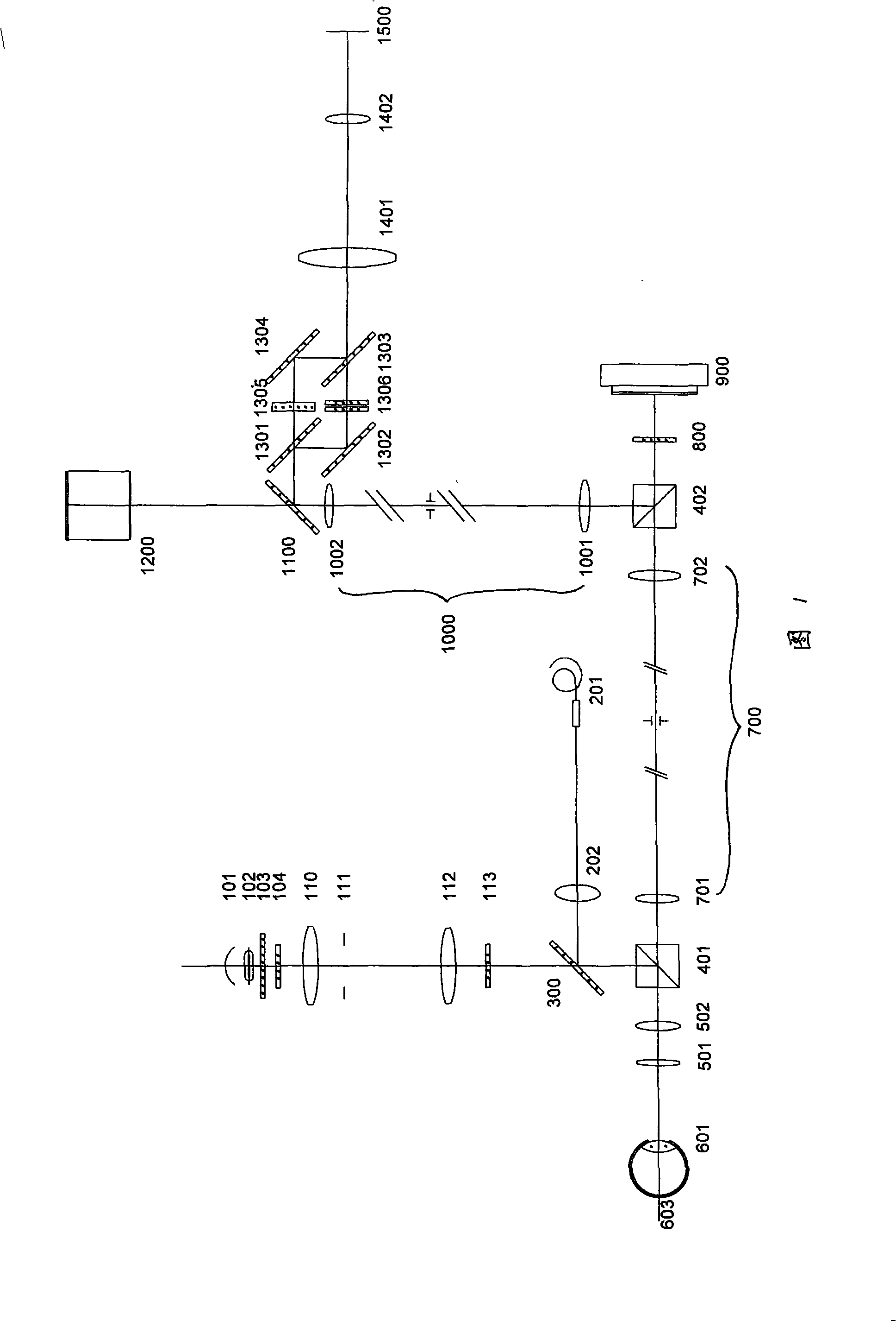
[0015] Embodiment: As shown in FIG. 1 , a retinal cell microscopic imaging system capable of layered scanning includes an illumination system, a layered scanning optical unit, and a microscopic imaging optical unit.

[0016] From the illumination system (as shown in Figure 1, composed of reflector 101 to bandpass filter 113), the parallel incident light beam is reflected by the first polarization beam splitting prism PBS 401, enters the layered scanning optical unit, and then passes through the human body. The eye diopter focuses.

[0017] The layered scanning optical unit includes a first objective lens 501 and a second objective lens 502 . Wherein, the first objective lens 501 and / or the second objective lens 502 can move with a precise distance. In this embodiment, the first objective lens 501 is chosen to be fixed, and the second objective lens 502 can move precisely along the axial direction.

[0018] The layered scanning optical unit can not only adjust the diopter of ...


PUM


Abstract

The present invention discloses a retina cell microscopic imaging system which can conduct stratified scanning and comprises an illuminating system and a microscopic imaging optical unit. The inside of an optical path between the illuminating system and a human eye (601) is provided with a stratified scanning optical unit which comprises a first object lens (501) and a second object lens (502). The first object lens (501) and/or the second object lens (502) can move critically along the axial direction. The parallel incident illumination beams of the illuminating system are focused on certain film inside a human eye retina (603) through the second object lens (502) and the first object lens (501) sequentially. During the stratified scanning, a focusing face formed on the retina (603) moves correspondingly at each cell layer inside the retina (603) along with the movement of the first object lens (501) and the second object lens (502). A small depth of focus imaging optical unit is used as the microscopic imaging optical unit. The retina cell microscopic imaging system of the present invention has simple structure and can effectively conduct stratified observation towards each film forming the retina.

Description

technical field [0001] The invention relates to a retinal cell microscopic imaging system, in particular to a retinal cell microscopic imaging system capable of layered scanning. Background technique [0002] In the existing microscopic imaging system of retinal cells, no layered scanning of the retina is involved. For example: the retinal cell microscopic imaging system described in patents CN99115051.1, CN99115052.X, CN99115053.8 and CN99115054.6 of the Institute of Optoelectronic Technology, Chinese Academy of Sciences. [0003] Since the retina is a phase-type, transparent tissue structure with a total thickness of only a few hundred microns, there are multi-layer structures distributed within this thickness range, and each layer is distributed with different cell tissues. The distribution of various cells and their Changes are closely related to diseases and their changes, so it is desirable to have a layered view of the layers that make up the retina. In fact, if the...

Claims


Application Information

Patent Timeline
IPC IPC(8): A61B3/13A61B3/12
Inventor 周明宝张运海朱磊
Owner 江阴龙跃信息科技有限公司
Why Eureka
Try Eureka