Steel reinforced concrete fore shaft beam and method for supporting foundation pit

A technology of reinforced concrete and lock beams, which is applied in excavation, infrastructure engineering, construction, etc., can solve the problems of high cost, non-reusable lock beams, and large steel consumption of steel structure lock beams, and achieve easy recycling and high rigidity Large, the effect of increasing the support height

Inactive Publication Date: 2008-10-29
CENT SOUTH UNIV
View PDF1 Cites 2 Cited by
  • Summary
  • Abstract
  • Description
  • Claims
  • Application Information

AI Technical Summary

Problems solved by technology

[0004] The purpose of the present invention is to solve the problem that ordinary concrete lock beams cannot be reused, while steel structure lock beams use a large amount of steel and have high costs, and propose a lock that can not only give full play to the mechanical properties of materials, but also save costs by reusing steel materials. Mouth beam

Method used


Image

  • Steel reinforced concrete fore shaft beam and method for supporting foundation pit
  • Steel reinforced concrete fore shaft beam and method for supporting foundation pit
  • Steel reinforced concrete fore shaft beam and method for supporting foundation pit

Examples


Embodiment 1

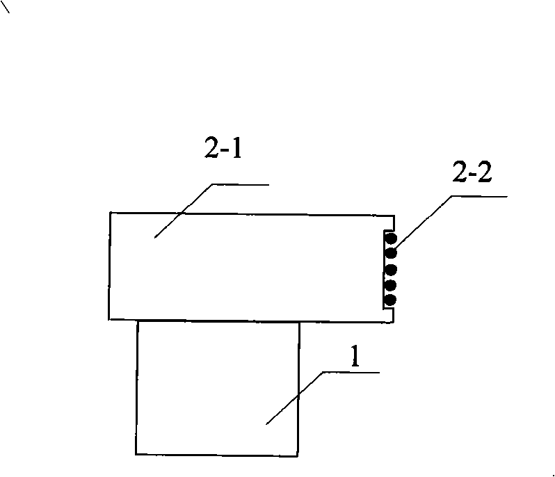
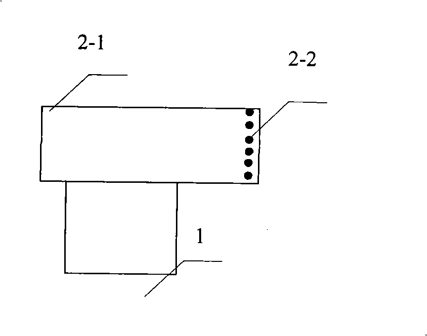
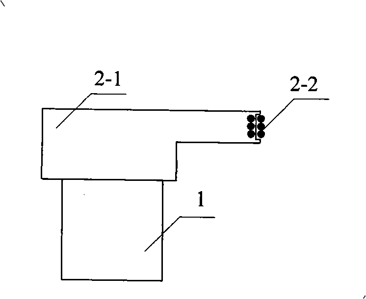
[0018] See attached Figure 1~6 , use concrete 2-1 and prestressed steel bars 2-2 to prepare reinforced concrete interlocking beams, and the lateral cross section of interlocking beams can be rectangular (see attached figure 1 , attached figure 2 And attached Figure 5 ), in order to save material, the lateral cross-section of the locking beam can also be T-shaped (see attached Figure 4 ) or L-shaped (see attached image 3 ) and other constant or variable cross-sections of various transformation shapes. The prestressed steel bars are longitudinally installed inside the side of the locking beam close to the foundation pit (see attached figure 2 ), can also be installed longitudinally on the surface of the locking beam near the foundation pit side (see attached figure 1 ), it can also be installed inside and on the surface of the side of the locking beam close to the foundation pit (see attached image 3 , attached Figure 4 , attached Figure 5 And attached Image 6...

Embodiment 2

[0020] The method for applying the reinforced concrete locking beam of the present invention to support the foundation pit is specifically implemented as follows: Excavate the foundation groove, construct the guide wall in the foundation groove according to the design requirements; construct the support structure 1, the support structure can be row piles or continuous Wall or steel structure supporting piles; after the function of the guide wall is completed, remove the guide wall; install the prestressed reinforced concrete lock beam 2 on the upper end of the support structure 1, and specifically adopt the post-tensioning method to construct the lock beam: install the formwork first, Then locate and install the prestressed steel bars 2-2 with sleeves, and then pour concrete 2-1. After the concrete reaches the curing age, stretch the prestressed steel bars in batches and anchor them with anchors 2-3. The cantilever support structure is connected as a whole with the lock beam, a...

example 2

[0021] Example 2: Reference figure 2 , Figure 5 with Figure 7 , The foundation pit support method of this example is the same as that of Example 2.


PUM


Abstract

The invention discloses a reinforced concrete locking beam and a method for supporting a foundation trench using the same. The locking beam is composed of concrete and reinforcement, wherein the prestressed reinforcement with a sleeve is vertically installed on one side of the locking bean close to the foundation trench. The method for supporting the foundation trench using the locking beam comprises the steps of: constructing the locking beam by the post-tensioning method, connecting a cantilever type supporting structure as a whole, supporting the two ends of the locking beam on the trench wall or a supporting pile, and fixing with an anchor rod or an anchor rope; and excavating the planar foundation trench. The inventive locking beam can give full play to the tension resistant role of the prestressed reinforcement, which can be easily recovered and repeatedly used; and has high side-movement resisting stiffness and high carrying capacity. The inventive method for supporting the foundation trench using the locking beam is better than the method using internal stays, and is better and simpler than the method by dragging anchors due to the reusability of the prestressed reinforcement and easy controllability of the supporting conditions at the two ends of the locking beam.

Description

technical field [0001] The invention relates to the fields of civil engineering and construction engineering, in particular to a locking beam and a method for supporting foundation pits using the same. Background technique [0002] At present, in the field of civil engineering and construction engineering, the lock beams in the foundation pit support or slope support mainly adopt ordinary concrete lock beams (or crown beams), which are usually only used as a temporary support. The support structure connects the support structure as a whole. Due to the limited lateral support capacity of this support structure, it is usually only designed and constructed according to the structural requirements, and the mechanical properties of the material are not fully utilized. And the foundation pit support is a temporary structure, which is usually used once and cannot be reused. Due to the large cross-section of the lock beam, there are many steel bars inside, which results in serious ...

Claims


Application Information

Patent Timeline
IPC IPC(8): E02D17/04
Inventor 张可能黎永索曾旺辉
Owner CENT SOUTH UNIV
Why Eureka
Try Eureka