
Construction method for embedding thermal insulation in concrete structure exterior wall surface

A technology of concrete structure and construction method, applied in the direction of thermal insulation, wall, building components, etc., can solve the problems of not achieving good thermal insulation effect, cracking on the outer surface of the building, affecting the appearance, etc. Degree, beautiful appearance effect

Inactive Publication Date: 2008-10-29
HENAN NO 1 CONSTR ENG GRP
View PDF0 Cites 36 Cited by
  • Summary
  • Abstract
  • Description
  • Claims
  • Application Information

AI Technical Summary

Problems solved by technology

[0002] Exterior wall insulation technology is widely used in current construction projects, but because the insulation layer is placed outside the structural surface, and it is mostly connected to the wall by bonding, due to the influence of natural conditions such as wind and sun, the insulation layer cannot The service life is the same as that of the wall structure layer, and quality problems such as cracking and peeling of the outer surface of the building often occur within the design service life, which does not achieve a good thermal insulation effect and affects the appearance

Method used


Image

  • Construction method for embedding thermal insulation in concrete structure exterior wall surface
  • Construction method for embedding thermal insulation in concrete structure exterior wall surface
  • Construction method for embedding thermal insulation in concrete structure exterior wall surface

Examples


Embodiment

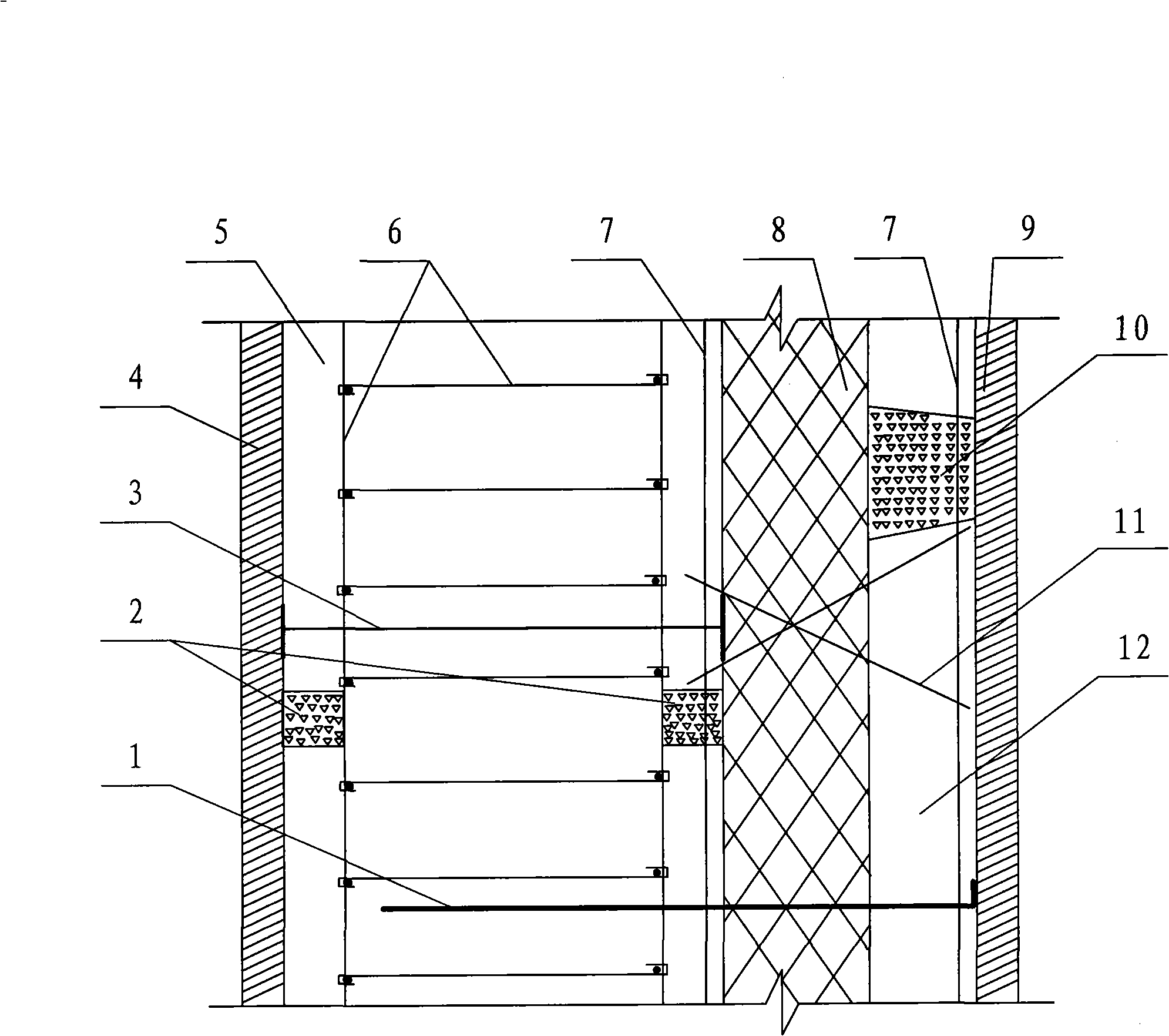
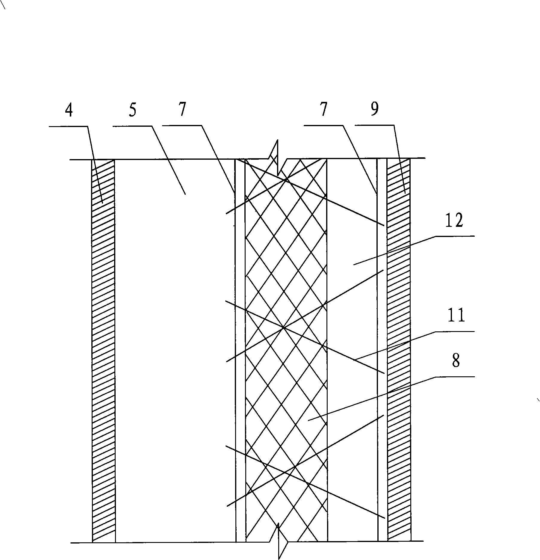
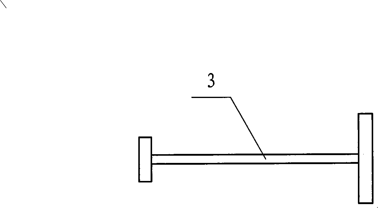
[0034] Example: see Figure 1-Figure 5 , in the figure, 1-auxiliary fixing rod, 2-concrete pad, 3-steel frame, 4-inner formwork, 5-wall, 6-wall structure reinforcement, 7-reinforcing mesh, 8-polystyrene board, 9-outer formwork, 10-concrete cushion block, 11-steel bar (belly wire), 12-self-tight high-performance concrete body.

[0035] In the present invention, the built-in thermal insulation layer of the concrete structure is a structure in which two layers of steel mesh 7 are sandwiched between polystyrene boards 8 and then three-dimensional obliquely inserted steel bars 11 are welded into thermal insulation grid panels, and concrete is poured on both sides at the same time. The polystyrene board 8 is an extruded polystyrene board.

[0036] The construction method of the built-in insulation layer on the outer wall of the concrete structure includes the following steps:

[0037] a. Fabrication of the thermal insulation grid plate: the polystyrene board 8 is placed between tw...


PUM

PropertyMeasurementUnit
Thicknessaaaaaaaaaa

Abstract

The invention discloses a construction method of a concrete structure external wall with a built-in thermal insulating layer. The construction method comprises the steps of putting polystyrene plates among multiple layers of reinforcing meshes, obliquely inserting reinforcing steel bars in three-dimensional direction, welding the steel bars to obtain a thermal insulating wire rack board, and simultaneously pouring concrete on both internal and external sides to form a structural system. The specific construction method comprises the steps of: fabricating the thermal insulating wire rack board, banding external wall boundary members (embedded columns) and external wall board steel bars, installing the thermal insulating wire rack board, connecting steel bars around the thermal insulating wire rack board and laying pipelines, installing and fixing steel struts on the inner side of the thermal insulating wire rack board and cushion blocks on the outer side of the thermal insulating wire rack board, erecting inner templates for an external wall, erecting outer templates for the external wall, testing, simultaneously pouring concrete at both the internal side and the external side, removing templates, and curing. The inventive concrete structure external wall with the built-in thermal insulating layer has the advantages of solid connection, good sound insulating and thermal insulating effects, long service life, simple construction method, good shock resistant effect, short construction time, environmental friendliness, low construction cost, and good social and economic benefits; and is suitable for various urban residential buildings.

Description

1. Technical field: [0001] The invention relates to a building construction method, in particular to a construction method for a built-in insulation layer on the exterior wall of a concrete structure. 2. Background technology: [0002] Exterior wall insulation technology is widely used in current construction projects, but because the insulation layer is placed outside the structural surface, and it is mostly connected to the wall by bonding, due to the influence of natural conditions such as wind and sun, the insulation layer cannot It has the same service life as the wall structure layer, and quality problems such as cracking and peeling of the outer surface of the building often occur within the design service life, which does not achieve a good thermal insulation effect and affects the appearance. 3. Contents of the invention: [0003] The technical problem to be solved by the present invention is to overcome the deficiencies of the prior art, and provide a constructio...

Claims


Application Information

Patent Timeline
IPC IPC(8): E04B1/80E04B2/00E04B2/84
Inventor 王虎王建伟金红伟张志明王雁钧谢继义
Owner HENAN NO 1 CONSTR ENG GRP
Learn More