Surface gas flow purging thermal desorption sampling device

A technology of airflow purging and sampling device, which is applied in the field of sampling device of ion mobility spectrometer, can solve the problems of not being suitable for on-site rapid analysis, unable to directly analyze solid and liquid samples, etc., and achieves a reasonable structure and wide applicability. Effect

Inactive Publication Date: 2008-10-29
DALIAN INST OF CHEM PHYSICS CHINESE ACAD OF SCI
View PDF0 Cites 24 Cited by
  • Summary
  • Abstract
  • Description
  • Claims
  • Application Information

AI Technical Summary

Problems solved by technology

[0003] Generally, it is only suitable for direct analysis of gaseous samples, not solid and liquid samples
In actual work, many solid and liquid samples require rapid and on-site analysis and detection by ion mobility spectrometers. Usually

Method used


Image

  • Surface gas flow purging thermal desorption sampling device

Examples


Embodiment 1

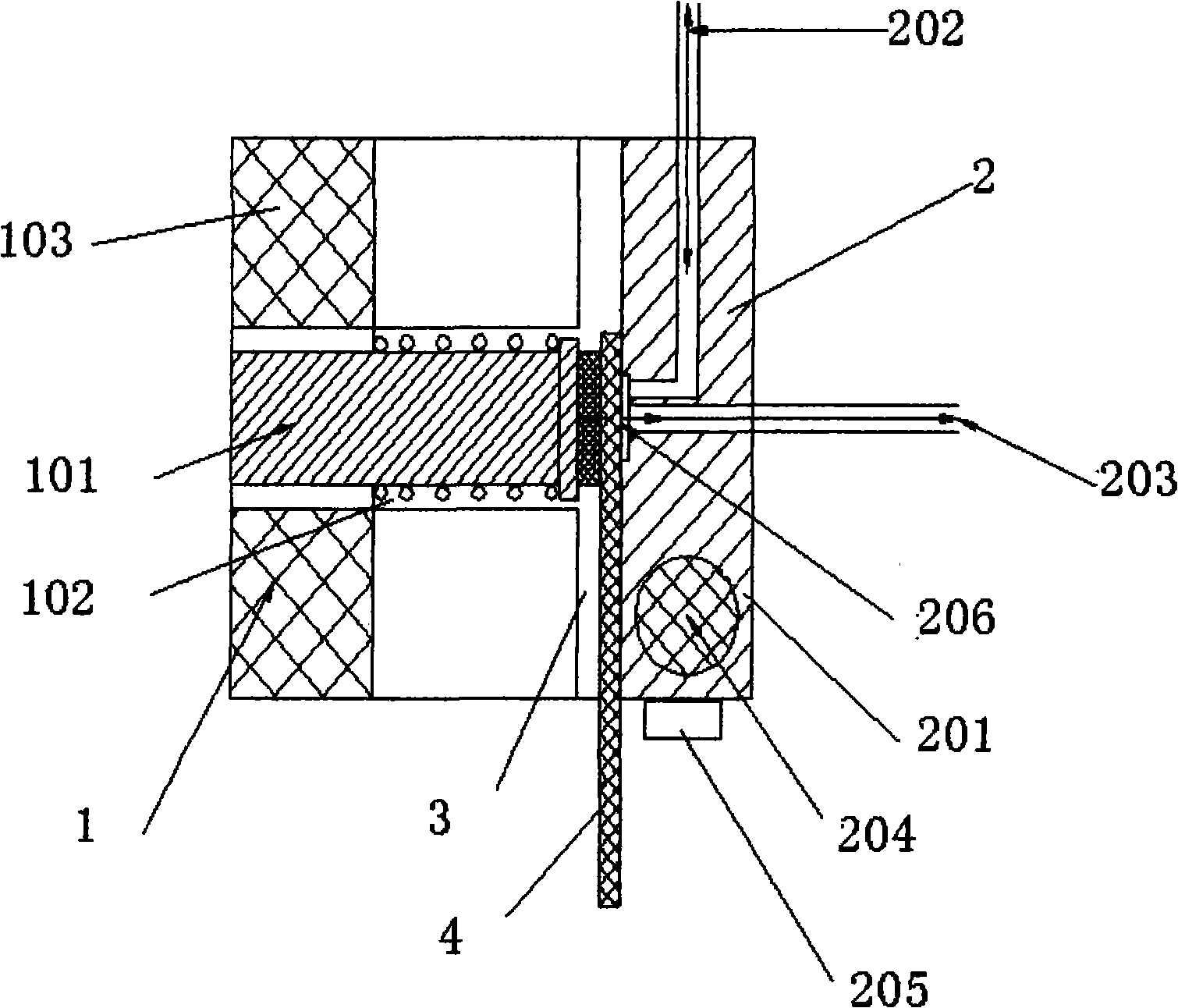
[0022] A surface air flow purging thermal desorption sampling device, characterized in that: the surface air flow purging thermal desorption sampling device includes a fixed control device (1) for controlling whether the sample attachment sheet is clamped or not, The surface airflow purging device (2), the gap formed between the two is a sample slot (3) for inserting a sample attachment sheet; between the fixed control device (1) and the surface airflow purging device (2) Fixed connection.

[0023] The surface air flow purging device (2) includes a thermal analysis body (201), a gas channel one (202), a gas channel two (203), a heating rod (204), a temperature control device (205), a thermal The surface air flow formed between the concave part of the analysis body (201) and the sample attachment sheet sweeps the thermal analysis cell (206);

[0024] Gas channel 1 (202) and gas channel 2 (203) are fixedly connected inside the thermal analysis body (201) respectively, and the h...

Embodiment 2

[0029] A surface air flow purging thermal desorption sampling device, characterized in that: the surface air flow purging thermal desorption sampling device includes a fixed control device (1) for controlling whether the sample attachment sheet is clamped or not, The surface airflow purging device (2), the gap formed between the two is a sample slot (3) for inserting a sample attachment sheet; between the fixed control device (1) and the surface airflow purging device (2) Fixed connection.

[0030] The surface air flow purging device (2) includes a thermal analysis body (201), a gas channel one (202), a gas channel two (203), a heating rod (204), a temperature control device (205), a thermal The surface air flow formed between the concave part of the analysis body (201) and the sample attachment sheet sweeps the thermal analysis cell (206);

[0031] Gas channel 1 (202) and gas channel 2 (203) are fixedly connected inside the thermal analysis body (201) respectively, and the h...

Embodiment 3

[0036] A surface air flow purging thermal desorption sampling device, characterized in that: the surface air flow purging thermal desorption sampling device includes a fixed control device (1) for controlling whether the sample attachment sheet is clamped or not, The surface airflow purging device (2), the gap formed between the two is a sample slot (3) for inserting a sample attachment sheet; between the fixed control device (1) and the surface airflow purging device (2) active connection.

[0037] The surface air flow purging device (2) includes a thermal analysis body (201), a gas channel one (202), a gas channel two (203), a heating rod (204), a temperature control device (205), a thermal The surface air flow formed between the concave part of the analysis body (201) and the sample attachment sheet sweeps the thermal analysis cell (206);

[0038] Gas channel 1 (202) and gas channel 2 (203) are respectively fixedly connected inside the thermal analysis body (201), the heat...


PUM


Abstract

The invention relates to a thermal desorption sampling device used for surface airflow purging which is characterized by comprising a fixed control device (1) used for controlling whether a sample attachment sheet is clamped tightly, a surface airflow purging device (2) and a clipping seam which is formed between the fixed control device (1) and the surface airflow purging device (2) and is used for inserting a sample channel (3) of the sample attachment sheet; the fixed control device (1) and the surface airflow purging device (2) are connected with each other fixedly or movably; the sampling device provided by the invention can meet the sampling requirement of solid and liquid samples, can realize automatic operation, complete the steps of heating, sampling and analysis needed by the sampling in short time and meet the need that an ion mobility spectrometer carries out fast and on-spot analysis detection; the device provided by the invention has fastness, effectiveness, reasonable structure and wide application, and can provide gas samples for various gas analyzers.

Description

technical field [0001] The invention relates to a sampling device of an ion mobility spectrometer, in particular, it belongs to a device for converting solid and liquid samples into gas for sampling in gas analysis instruments. Background technique [0002] Ion Mobility Spectrometry (IMS) technology is a separation and detection technology that appeared abroad in the 1970s, and was applied to on-site analysis and detection in the 1980s. The gas sample is ionized to form ions, which then drift in an applied electric field. Due to the different mobilities of different samples, the different components in the sample are separated in the transfer tube, and in general, heavier molecules travel slower than lighter molecules. In this way, the composition of the sample can be known from the measured migration time. [0003] Generally, it is only suitable for direct analysis of gas samples, but not for solid and liquid samples. In actual work, many solid and liquid samples require...

Claims


Application Information

Patent Timeline
IPC IPC(8): G01N27/62G01N1/28G01N27/622
Inventor 李海洋王海龙李京华刘广生何川仙
Owner DALIAN INST OF CHEM PHYSICS CHINESE ACAD OF SCI
Why Eureka
Try Eureka