

Interconnection line failure detecting method
A detection method and interconnection line technology, applied in the direction of measuring electricity, measuring devices, measuring electrical variables, etc., can solve the problems of unsatisfactory detection requirements, slow interconnection speed, etc., and achieve accurate positioning and high detection efficiency.
- Summary
- Abstract
- Description
- Claims
- Application Information
AI Technical Summary
Problems solved by technology
Method used
Image

Examples
Embodiment 1
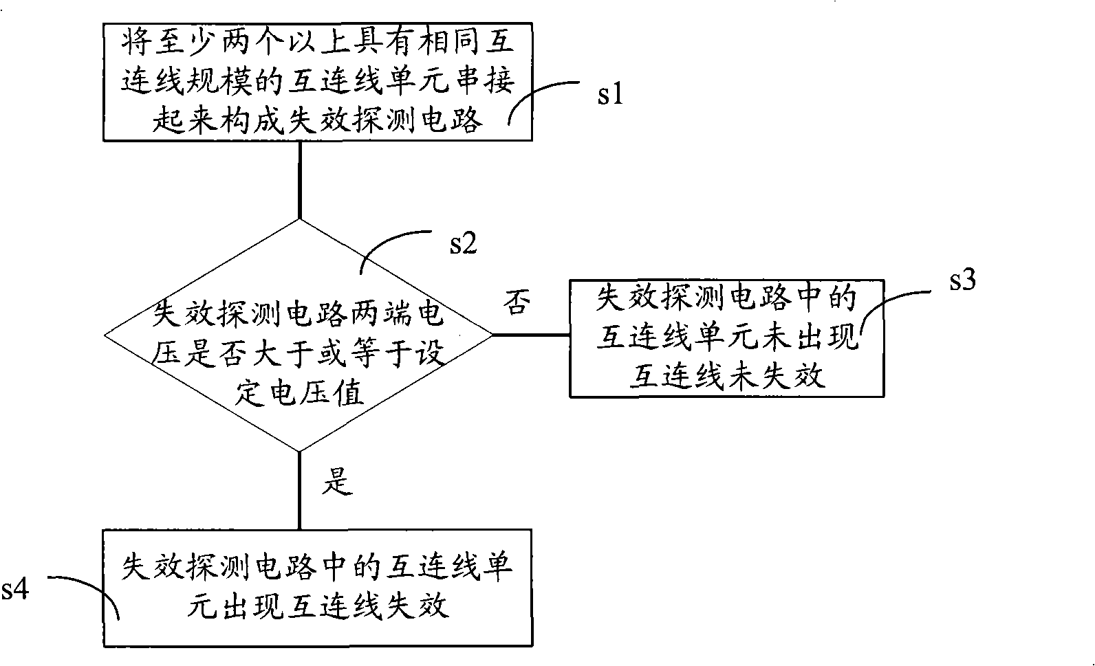
[0028] Example 1, such as figure 2 As shown, the interconnection failure detection method in Embodiment 1 of the present invention includes the following steps,
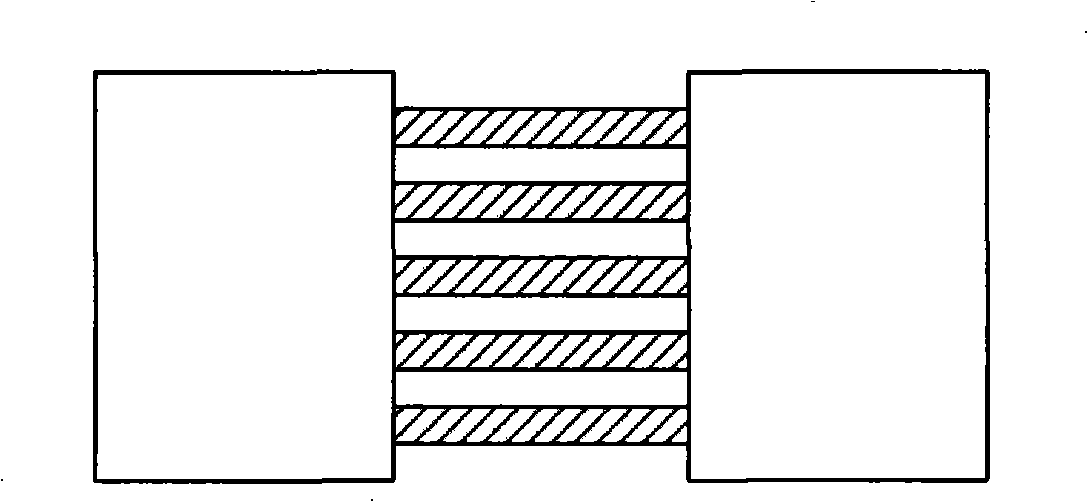
[0029] In step s1, at least two or more interconnection units with the same interconnection scale are connected in series to form a failure detection circuit. Because the electromigration phenomenon mentioned above can only be found in the interconnection line of a certain length, the scale of the selected interconnection line unit is actually determined according to the research needs of the electromigration phenomenon of the interconnection line of a specific length. . Embodiment 1 of the present invention still adopts such as in order to make description convenient figure 1 Copper interconnect line unit shown. For example, suppose figure 1 Each 400 micron copper interconnect shown has a resistance of 500Ωm, then if figure 1 The minimum interconnection unit formed by connecting five copper interconnections in...
Embodiment 2
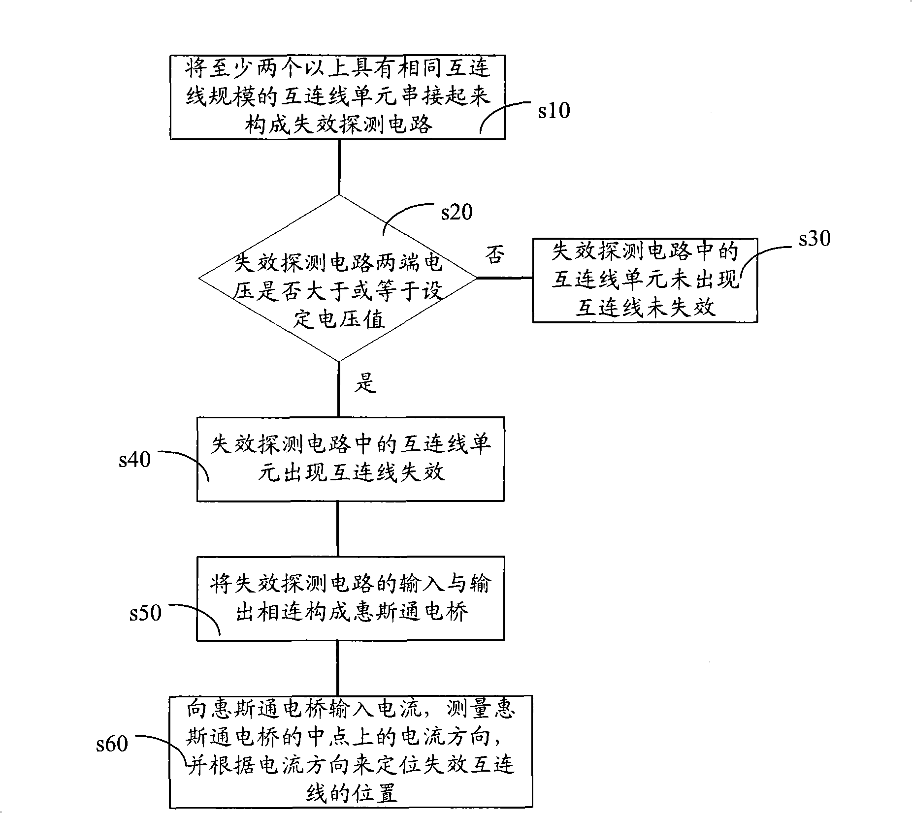
[0036] Example 2, such as image 3 As shown, the interconnection failure detection method in Embodiment 2 of the present invention includes the following steps,
[0037] In step s10, at least two or more interconnection units with the same interconnection scale are connected in series to form a failure detection circuit. Because the electromigration phenomenon mentioned above can only be found in the interconnection line of a certain length, the scale of the selected interconnection line unit is actually determined according to the research needs of the electromigration phenomenon of the interconnection line of a specific length. . Embodiment 2 of the present invention still adopts such as figure 1 Copper interconnect line unit shown. For example, suppose figure 1 Each 400 micron copper interconnect shown has a resistance of 500Ωm, then if figure 1 The minimum interconnection unit formed by connecting five copper interconnections in parallel is equivalent to an equivalent...
PUM
 Abstract
Description
Claims
Application Information