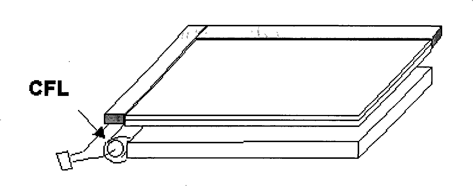
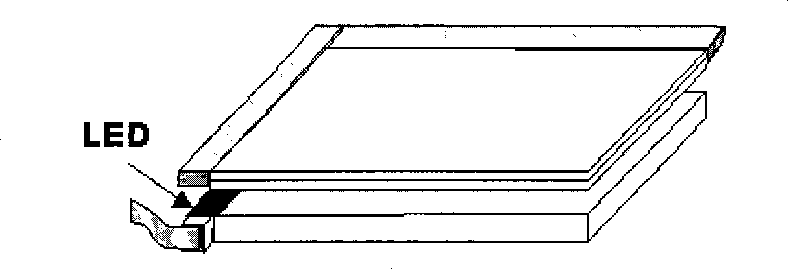
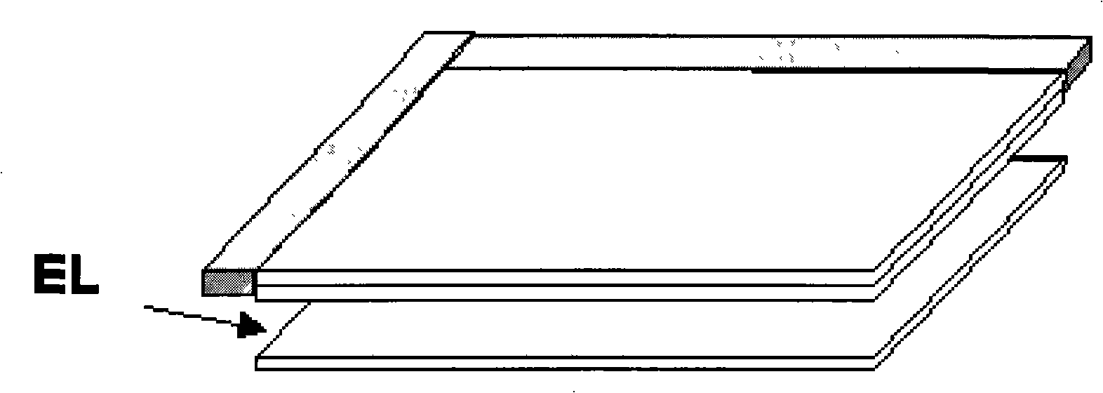
LCD and back light source thereof

A liquid crystal display and liquid crystal display technology, applied in the direction of light source, electric light source, electroluminescent light source, etc., can solve the problem of poor uniformity of light emission of the screen body, uneven distribution of current of the light source screen body, and affecting the LCD display effect OLED backlight light emission stability In order to achieve the effect of reducing power consumption, improving uniformity and luminous stability, and improving display effect

Inactive Publication Date: 2008-10-29
KUNSHAN VISIONOX DISPLAY TECH +2
View PDF0 Cites 24 Cited by
  • Summary
  • Abstract
  • Description
  • Claims
  • Application Information

AI Technical Summary

Problems solved by technology

[0008] However, in the prior art, the OLED backlight source for LCD adopts a whole-surface light-emitting method. Since the anode of the OLED device generally uses a transparent electrode ITO with a relatively large resistance, and the OLED itself is a current injection device, it causes a large The current distribution of the area light source screen is not uniform, resulting in poor uniformity of light emission on the entire screen, which in turn affects the LCD display effect and the light stability of the OLED backlight itself.
Moreover, since the full-surface light-emitting OLED backlight is always in a bright state during the LCD display process, this will inevitably lead to a relatively large power consumption of the OLED backlight.

Method used


Image

  • LCD and back light source thereof
  • LCD and back light source thereof
  • LCD and back light source thereof

Examples


Embodiment 1

[0029] Such as image 3 As shown, each pixel in the OLED backlight panel is matched with one sub-pixel in each pixel in the LCD panel. A sub-pixel such as 1-1, 1-2 and 1-3 has exactly the same size and positions corresponding to each other. In this way, when the 1-1, 2-2, and 3-2 pixels in the liquid crystal display device are in need of display, the corresponding OLED backlight 1W, 2W, and 3W pixels are in a light-emitting state, and other pixels on the OLED are not emitting light. .

Embodiment 2

[0031] Such as Figure 4 As shown, each pixel in the OLED backlight panel matches each pixel in the LCD panel, and the specific feature is the pixel size of a pixel on the OLED panel such as 4W and a sub-pixel of the LCD panel such as 1-1 The size is exactly the same and the position is one-to-one. In this way, when the sub-pixel 1-1 in the liquid crystal display device needs to display, the corresponding OLED backlight pixel 4W is in a light-emitting state, and other pixels on the OLED do not emit light.


PUM


Abstract

The invention relates to a liquid crystal display device, in particular to a liquid crystal display device adopting an organic electroluminescent device as the backlight, wherein, an organic electroluminescent panel taken as the backlight is a lattice luminescent screen. The pixel in the organic electroluminescent panel of the invention is set to be matched with the pixel in a liquid crystal panel. The liquid crystal display device of the invention can not only achieve the effect of reducing OLED backlight power consumption, but also greatly enhance the uniformity and luminescence stability of the backlight screen body as the OLD panel is designed to be lattice luminescence, and the liquid crystal display device is also beneficial to improving the display effect of the LCD devices.

Description

technical field [0001] The invention relates to a liquid crystal display, in particular to a liquid crystal display using an organic electroluminescence device as its backlight source, and belongs to the field of optoelectronic technology. Background technique [0002] With the continuous progress of the electronic industry, some traditionally bulky electronic products have gradually evolved to be portable. Reflecting on the display device, the liquid crystal display device (LCD) replaces the traditional cathode ray tube (CRT) display device and becomes the mainstream in the market. For some electronic products that are carried by individuals, such as mobile phones, PDAs, and notebook computers, it is even more impossible to use a traditional CRT display device as a display interface. [0003] LCD is a passive flat-panel display device. Since the LCD panel itself does not have luminous properties, a backlight must be added behind the LCD panel to achieve the display effect....

Claims


Application Information

Patent Timeline
Patent Type & Authority Applications(China)
IPC IPC(8): G02F1/13357H05B33/00G02F1/1335
Inventor 邱勇吴空物高裕弟
Owner KUNSHAN VISIONOX DISPLAY TECH
Why Eureka
Try Eureka