Device for cooling electric device mounted on vehicle
A technology for cooling devices and electronic equipment, which is applied in the layout of the cooling combination of electric devices and power devices, electric power devices, etc., can solve the problem of air temperature rise, cooling airflow temperature rise, electronic equipment cannot be effectively cooled and other problems, to achieve the effect of good cooling efficiency, reduce impact, and avoid large temperature rise
- Summary
- Abstract
- Description
- Claims
- Application Information
AI Technical Summary
Problems solved by technology
Method used
Image

Examples
no. 1 example
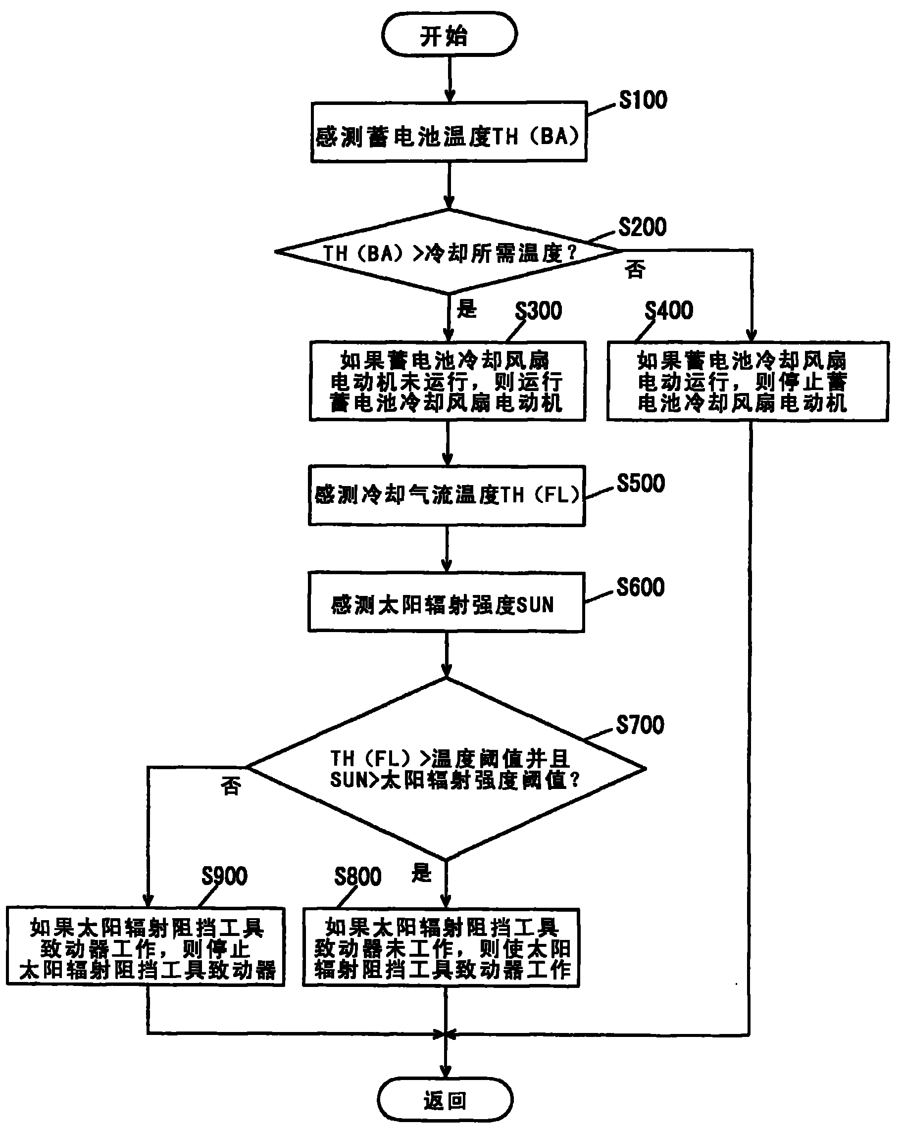
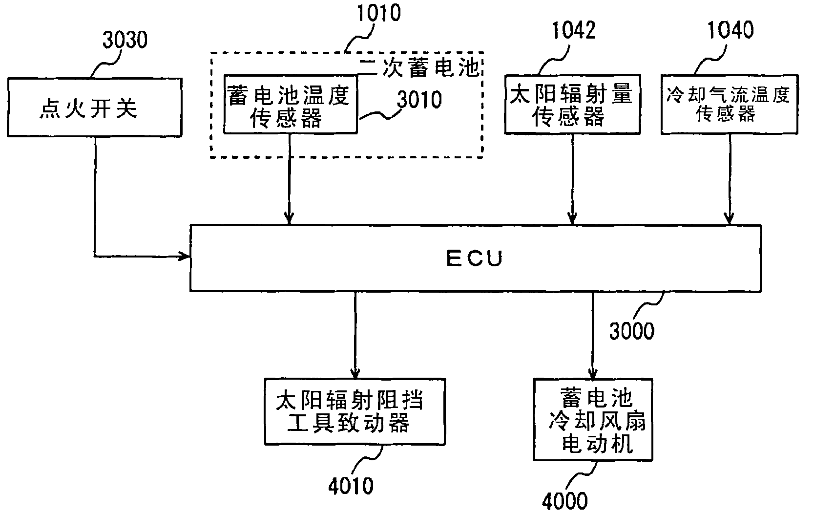
[0047] Embodiments of the present invention will be described below with reference to the accompanying drawings. In the following description, the same components are marked with the same symbols and have the same names and functions, so detailed descriptions will not be repeated. Note that although the following description is directed to a cooling device for cooling a battery (the battery is an energy storage mechanism, and the energy storage mechanism is an electronic device) on a vehicle, the present invention is not limited thereto. The energy storage mechanism can also be a capacitor, not limited to a storage battery; the electronic device can be a PCU including an inverter, a DC / DC converter, etc., and is not limited to an energy storage mechanism (battery, capacitor, etc.). In the following explanation, it is assumed that the vehicle is a hybrid vehicle using an engine and an electric motor as driving forces, however, the vehicle may also be an electric vehicle (EV) (t...
no. 2 example
[0081] FIG. 5 shows a vehicle cooling device 11000 mounted on a vehicle according to the present embodiment. Note that the same devices in Fig. 5 and Fig. 1 use the same symbols and have the same structure and function. Therefore, the detailed description will not be repeated here.
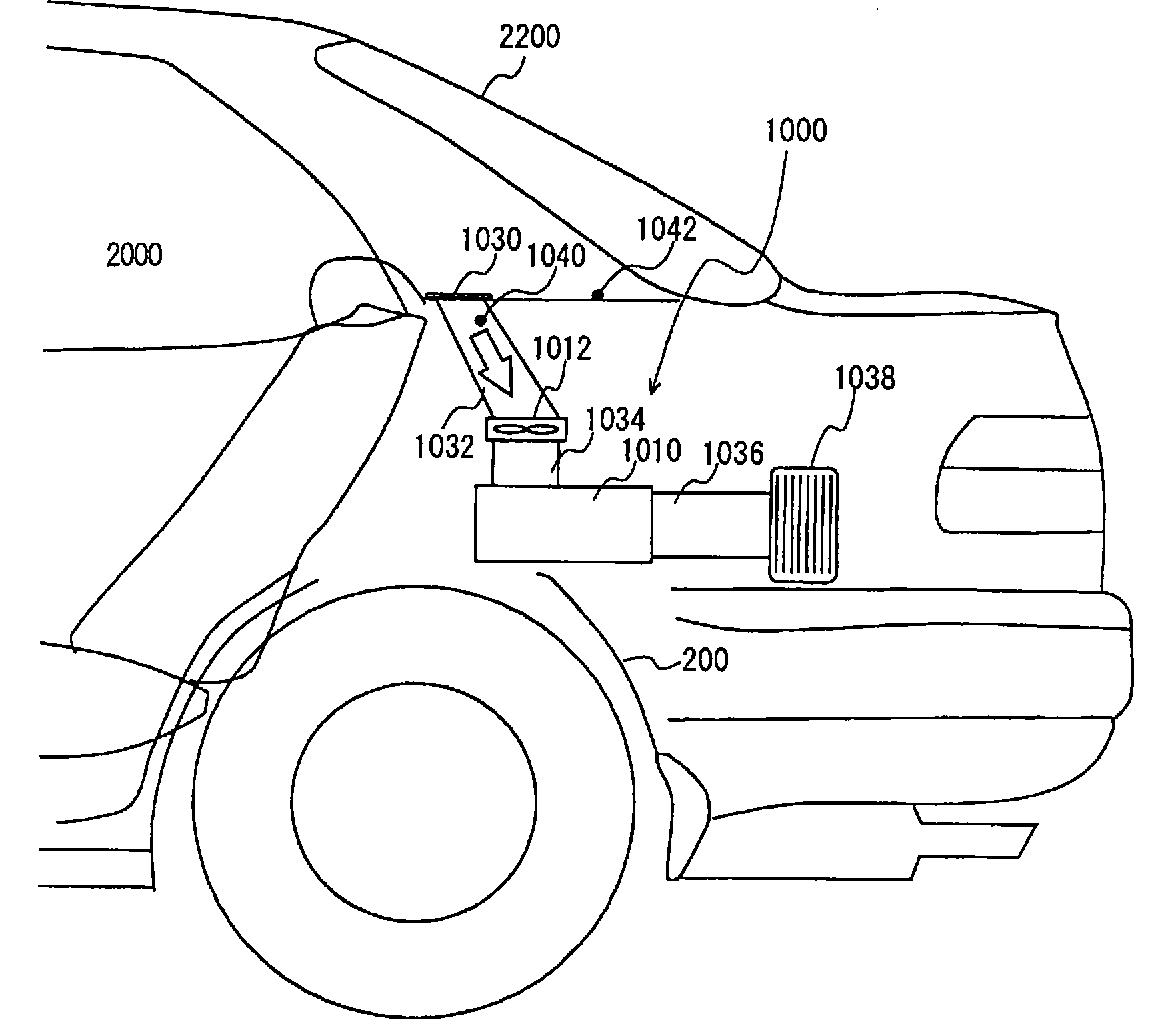
[0082] Referring to Fig. 5, Fig. 6 and Fig. 7, the plate-shaped element located on the rear window sill and capable of reflecting mid-infrared rays of solar radiation is described below: a reflector.
[0083] As shown in FIGS. 5 and 6, the reflective plate 11040 is located on the entire surface of the rear shelf. The reflector 11040 is a plate-shaped element consistent with the plane shape of the rear window platform, and its surface facing the rear windshield 2200 is processed into white or mirror to facilitate reflection of infrared rays.
[0084] In addition, as shown in FIGS. 5 and 7 , the reflection plate 11041 may also be arranged only near the air inlet 1030 of the rear window sill. The ...
PUM
 Abstract
Description
Claims
Application Information
 - R&D
- Intellectual Property
- Life Sciences
- Materials
- Tech Scout
- Unparalleled Data Quality
- Higher Quality Content
- 60% Fewer Hallucinations
Browse by: Latest US Patents, China's latest patents, Technical Efficacy Thesaurus, Application Domain, Technology Topic, Popular Technical Reports.
© 2025 PatSnap. All rights reserved.Legal|Privacy policy|Modern Slavery Act Transparency Statement|Sitemap|About US| Contact US: help@patsnap.com