Pipe sleeve anti-rotary dentistry implant

A technology for dental implants and implants, which is applied in the fields of dentistry, dental implants, medical science, etc., can solve the problem that the connection between the top of the implant shoulder and the abutment is not tight, it is not conducive to the early retention and osseointegration of cortical bone, and it is impossible to design Interpolation and other problems to achieve the effect of avoiding bone resorption, tightening in place, and increasing strength

Inactive Publication Date: 2008-11-05
FOURTH MILITARY MEDICAL UNIVERSITY
View PDF28 Cites 60 Cited by
  • Summary
  • Abstract
  • Description
  • Claims
  • Application Information

AI Technical Summary

Problems solved by technology

Although the inserting part can be designed to be as long as 2.5mm to 30mm, but due to the limitation of design factors such as the diameter of the implant, the thinner implant cannot be designed as an inserting type due to the strength of the superstructure, and many inserting types The design of the insertion part is also too short, such as implant products such as Alpha-bio, BEGO, Biohorizons, Zimmer, and TBR, as well as designs disclosed in patent documents such as WO2006109176A1, US20060172257A1, US7249949B2, US7104797B2, WO2006088291A1, WO2006012273A1, US62837253B1, A81, WO2006012273A1, US62837253B1, etc.
②In terms of anti-rotation design, most of the anti-rotation designs in the prior art are exposed on the top of the implant shoulder, such a

Method used


Image

  • Pipe sleeve anti-rotary dentistry implant
  • Pipe sleeve anti-rotary dentistry implant
  • Pipe sleeve anti-rotary dentistry implant

Examples


Embodiment Construction

[0037] The specific embodiment of the present invention will be further described in conjunction with accompanying drawing now:

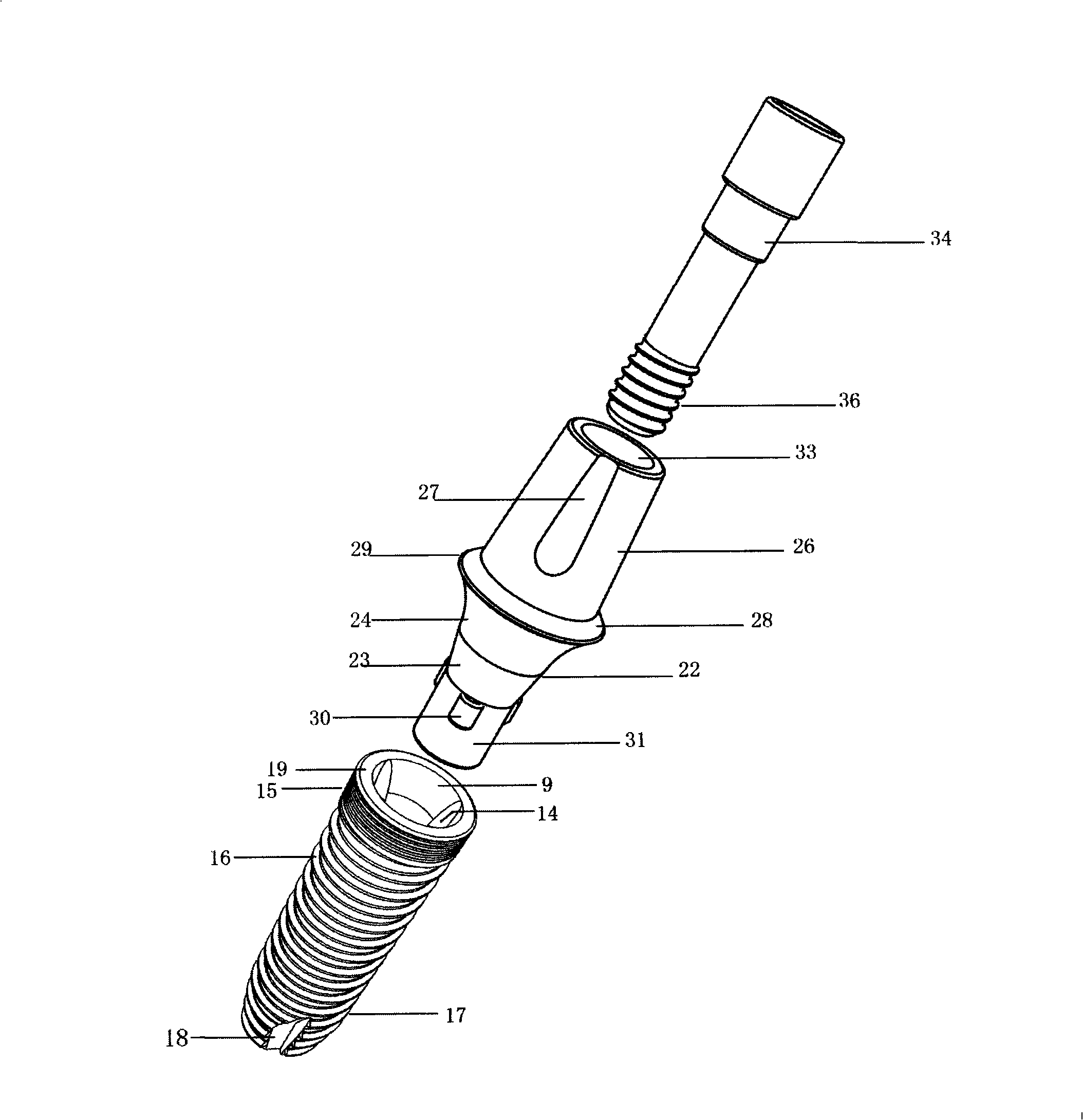
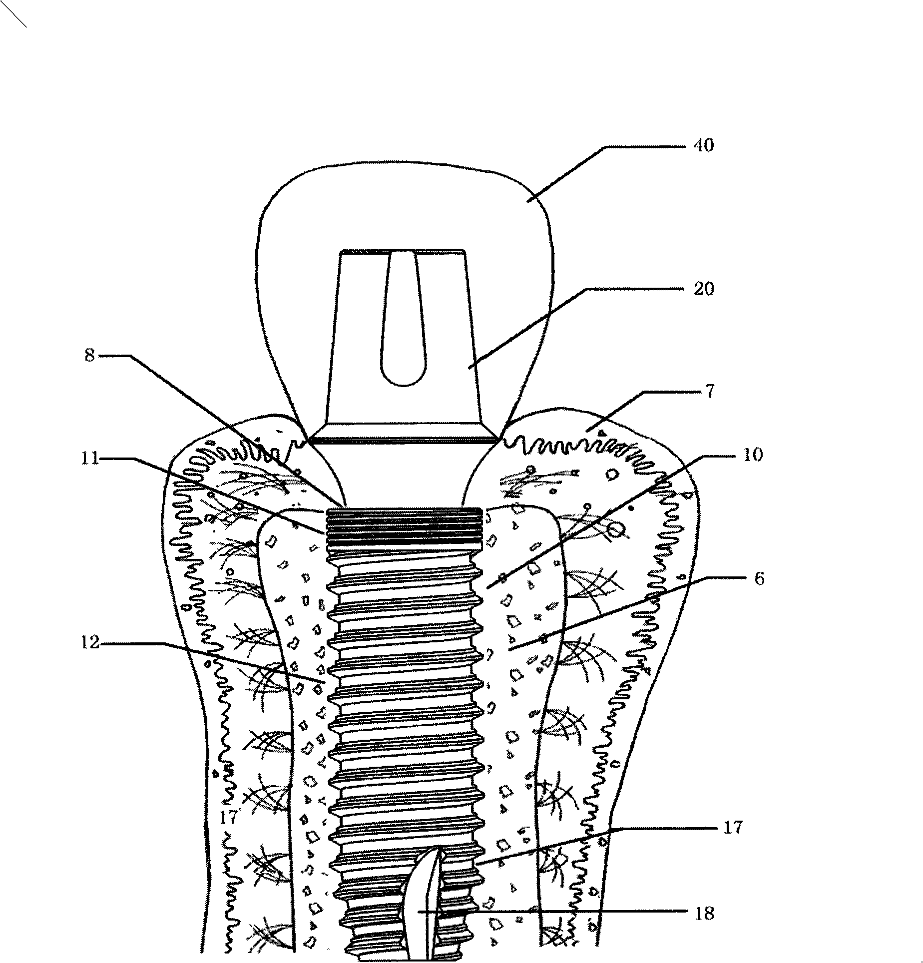
[0038] see figure 1 , Figure 10 : the pipe sleeve anti-rotation dental implant of the present invention has the implant part 10, the abutment part 20 and the central bolt 34, the outer circumference of the implant part 10 is a cylindrical helical design, and the abutment part 20 is installed on the part of the implant part in the form of a sleeve In the inner hole, a central bolt 34 connects the two as a whole.

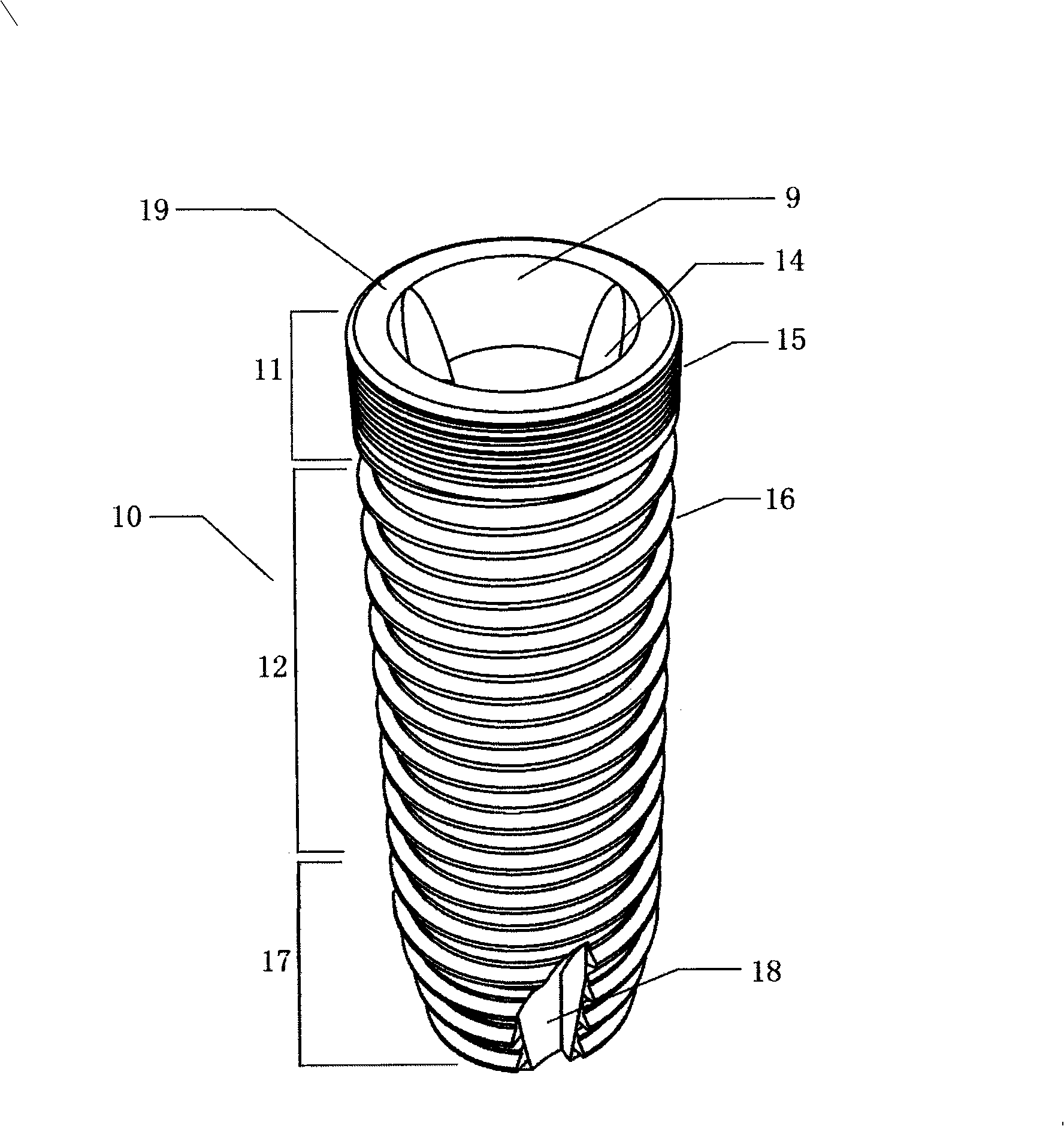
[0039] see figure 2 : In addition to increasing the bonding force and the bonding area between the implant body and the bone tissue 6, the double threads of the implant body part 12 can make the operation of screwing into the implant part more convenient and fast. It has a guiding effect to facilitate the implantation of the implant, and the self-tapping groove 18 is used to cut the bone wall and accommodate the cut bone chips therein....


PUM

PropertyMeasurementUnit
Taperaaaaaaaaaa
Diameteraaaaaaaaaa

Abstract

The invention relates to a dental implant, comprising an implant part, an abutment part and a central positioning bolt, which is characterized in that a peripheral cylindrical spiral body of the implant part is divided into three sections of an implant shoulder part, an implant main body part and an implant cone part, a self-tapping slot is formed on the cone part, an inner hole which can be inserted in the abutment part to form the inner intubation sleeve type connection is formed therein; the inner hole is divided into the upper section of a conical part, the middle section of an implant inner hole deep part and the lower section of an implant inner thread with the diameter less than that of the middle section; the abutment part is a rotary body which is sequentially reverse conical, positive curved, positive conical and cylindrical from top to bottom at the periphery, the abutment part can be a solid body and can also be the rotating body with a through hole which can be equipped with the central positioning bolt at the center, and the periphery thereof is a circular table which is sequentially reverse conical, positive curved, positive conical and cylindrical. The dental implant of the invention has rapid implantation, great strength, tight positioning and early retention, which can prevent the rotation, transfer the scattered bite force and scatter the stress function of the central bolt.

Description

technical field [0001] The invention belongs to the technical field of dental implants, and relates to a dental implant with fast implantation, high strength, early fixation and anti-rotation. Background technique [0002] Since the early 1980s, oral implantology has opened up a new field for the dental community, and implant restoration has become a rapidly developing and reliable means of restoration, and has gained an important position in the field of stomatology. In terms of periodontal disease treatment, we have broken the single treatment concept of blindly retaining the affected teeth in the past treatment process, and increased the dental implant treatment plan. In the field of prosthodontics, dental implant treatment helps to achieve a successful esthetic and functional restoration. In the field of orthodontics, the problem of moving teeth is easily solved by using implants as anchorages. As the artificial tooth root of the denture retention device, dental implan...

Claims


Application Information

Patent Timeline
IPC IPC(8): A61C8/00
Inventor 方巍刘宝林陈小文李德华宋应亮马威
Owner FOURTH MILITARY MEDICAL UNIVERSITY
Why Eureka
Try Eureka