
Nozzle for jet fabric dyeing machine

A jet dyeing machine technology, applied in liquid/gas/steam jet propulsion fabric, spray/jet textile material treatment, textile material treatment, etc., can solve dyeing unevenness and other problems

Active Publication Date: 2008-11-05
FONGS NAT ENG
View PDF0 Cites 3 Cited by
  • Summary
  • Abstract
  • Description
  • Claims
  • Application Information

AI Technical Summary

Problems solved by technology

This can also cause unevenness in staining

Method used


Image

  • Nozzle for jet fabric dyeing machine
  • Nozzle for jet fabric dyeing machine
  • Nozzle for jet fabric dyeing machine

Examples


Embodiment Construction

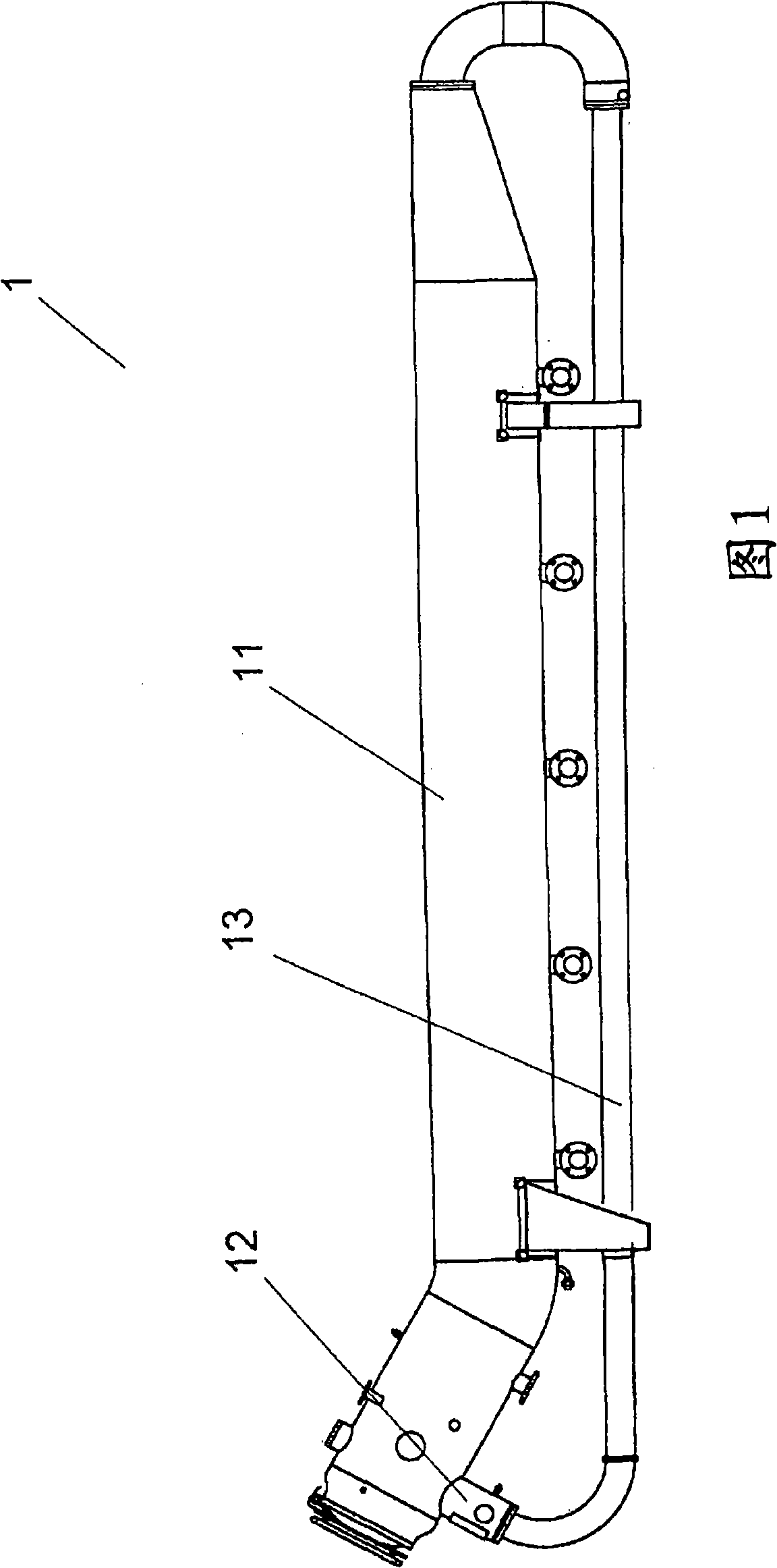
[0025] Fig. 1 shows a side view of an example of a conventional jet-type fabric dyeing machine. The machine 1 comprises a cylindrical main chamber 11 and a travel tube 13 of smaller diameter arranged below the main chamber 11 and connected to each end of the main chamber 11 . The main chamber 11 and the travel tube 13 thus form a continuous enclosed path around which endless fabric ropes can circulate while in contact with the dye liquor or another treatment fluid. The fabric is dyed or otherwise treated during the designated processing time that circulates around the machine.

[0026] The fabric rope is propelled around the machine along the travel path by a nozzle assembly 12 located at one end of the main chamber 11 at the entrance to the travel tube 13 . Nozzle assemblies traditionally comprise a tubular nozzle member through which the fabric passes (the nozzle member thereby forming part of the path of travel of the fabric). A jet of high pressure fluid (eg dye liquor o...


PUM


Abstract

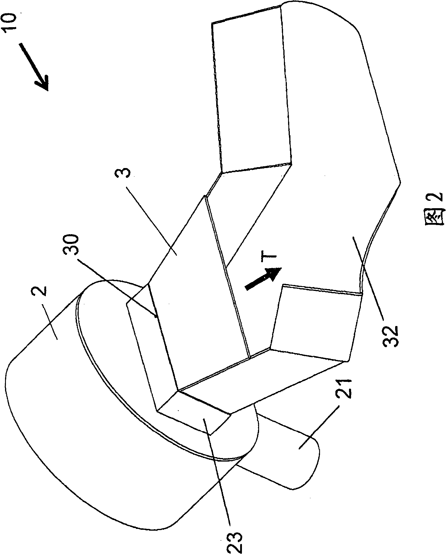
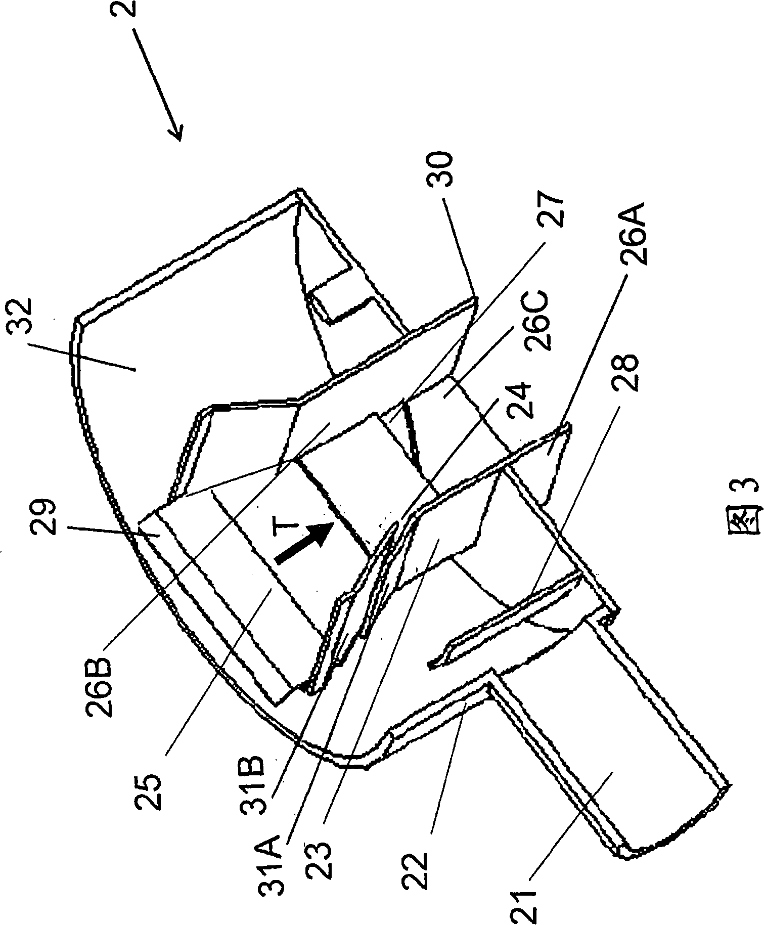
A nozzle assembly (10) for a jet fabric dyeing machine (1) comprises a tubular nozzle member through which fabric travels, the nozzle member defined by four side walls (26) and having a rectangular cross-section, and a nozzle gap (24) in a side wall (26A) of the nozzle member through which a jet of fluid can be applied to fabric in the nozzle member to propel the fabric along a travel path (T). An entry end (29) of the nozzle member has a decreasing cross-section to funnel fabric into the nozzle member, and an exit end (30) of the nozzle member has a rectangular guide tube (3) of expanding cross-section terminating in a fan-shaped trough (32). A fluid diverter (25, 27) intercepts part of the fluid jet and delivers it to a different side of the fabric.

Description

technical field [0001] The invention relates to a nozzle for a jet fabric dyeing machine. Background technique [0002] Fabrics are typically dyed in high speed jet dyeing machines. These machines comprise a series of tubes, conduits and chambers arranged in a communicating sequence to form an endless web travel path. A fabric formed as an endless rope is passed around this path and is propelled by one or more high-pressure fluid (dye liquor) jets directed onto the rope. [0003] The fluid jets are applied by a nozzle. The nozzle includes a tubular orifice through which the fabric cord passes. One or more gaps in the walls of the orifice direct the jet at high pressure onto the rope within the orifice and propel it forward along the path of travel. [0004] The design of this nozzle can be difficult. On the one hand, the nozzle should not take up too much space as this would take up too much fluid volume within the machine and affect the liquor ratio (the ratio of the v...

Claims


Application Information

Patent Timeline
IPC IPC(8): D06B23/00D06B1/02D06B3/28
CPCD06B3/28D06B3/20D06B3/24
Inventor 徐达明
Owner FONGS NAT ENG
Learn More