
Multi-functional window structure

A window structure and multi-functional technology, applied in the direction of windows/doors, building components, manual mechanisms, etc., can solve the problems of high building energy consumption, low waterproof performance of windows, high price, etc., and achieve the effect of solving potential safety hazards.

Active Publication Date: 2008-11-05
李京岐
View PDF0 Cites 43 Cited by
  • Summary
  • Abstract
  • Description
  • Claims
  • Application Information

AI Technical Summary

Problems solved by technology

Therefore, no matter how many sealing strips we use to seal between the window frame and the sash, these gaps cannot be completely eliminated. Therefore, this is also the main reason why my country's building energy consumption remains high, resulting in a large amount of heating in winter and a large amount of cooling in summer. These gaps are the main reason why the windows are not energy-saving and environmentally friendly, and the waterproof performance of the windows is not high due to these gaps. And because the current architectural design one-sidedly pursues a large lighting area, while ignoring the safety design of the height of the window sill, resulting in Now the window sills are getting lower and lower, some are only about 40, what’s more, the outer bay windows are designed with almost no window sills and a larger space is left in front of the windows for people to relax, so it is slightly If it is not enough, items will be blown down by strong winds, and people will fall from the window, resulting in countless people and property losses
[0003] Moreover, although the window technology on exterior buildings also adopts the window structure we applied, there are a large number of electronic security monitoring equipment abroad to make up for the structural defects on these windows. Although the price is expensive, it can play a positive role in real life.
Lessons learned in this area

Method used


Image

  • Multi-functional window structure
  • Multi-functional window structure
  • Multi-functional window structure

Examples


Embodiment Construction

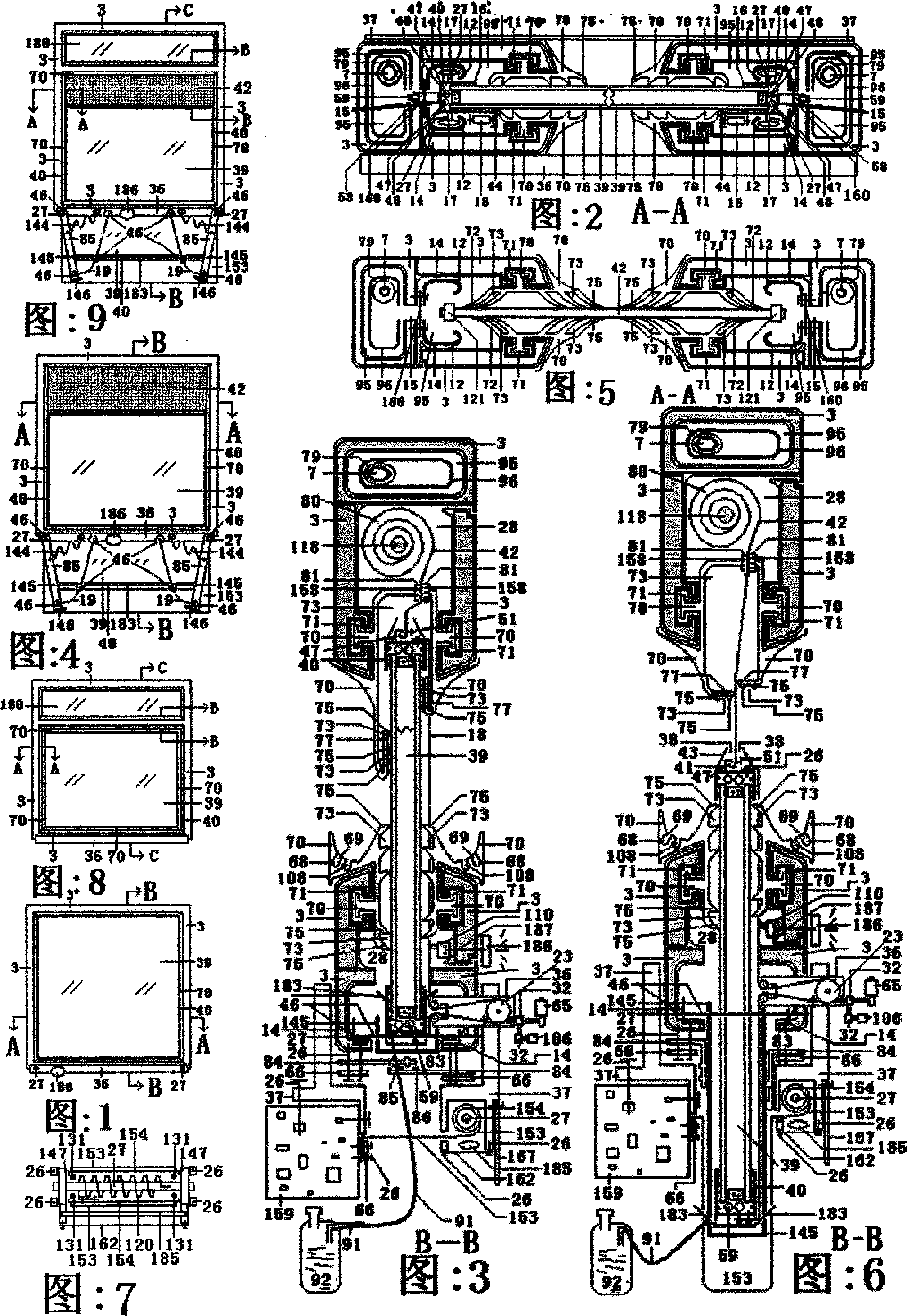
[0143] Figure 1 and Figure 2 and Figure 3 and Figure 4 and Figure 5 and Figure 6 and Figure 7 show a multifunctional window structure split window frame closed and open state structure diagram. Fig. 1, Fig. 2 and Fig. 3 are schematic diagrams of the split window frame being closed, and Fig. 4, Fig. 5 and Fig. 6 are schematic diagrams of the open state. It consists of split window frame 3, window sill bracket 36, glass 39, glass protective frame 40, main shaft body 1, window opening and closing device and sealing system 70, and invisible window screen 80 that can be completely hidden as main shaft body 1 mounting bracket. Shown in Fig. 1 is that the glass 39 that has glass protective frame 40, sealing strip 70 and window sill support 36 and switch window music prompting alarm device 186 are adorned in split window frame 3. Fig. 2 is a schematic cross-sectional view of plane A-A shown in Fig. 1 . In the internal cavity 95 of the split window frame 3 formed by the window frame p...


PUM


Abstract

A multifunctional window structure is composed of a window frame sectional material, a primary shaft main body, glass and a protective frame, a clean-free window screen, a primary shaft system, glass for cleaning indoors and outdoors automatically, an electric / manual switching mechanism locking state, an air filtering decompression device, a transparent, insulting, soundproof flexible rolling window which can be rolled up, double-layer flexible transparent curtain, a theft-proof telescopic guard rail, separated glass of the transparent insulating curtain, a transparent, insulating and soundproof flexible rolling door which can be rolled up. Glass (39) with the glass protective frame (40), a gland strip (70), a window sill bracket (36), a music promoting alarm (186) for opening and closingwindow, and a decorative cover (153) are installed in the separated window frame (3). The fully invisible window screen (42) and the glass (39) are connected actively. The steel cable (19) is installed on the glass protective frame (40). The upper bright band (180) is installed on the window frame sectional material (13).

Description

Technical field: [0001] The invention relates to a multi-functional window structure, which has a manual and electric way of opening and closing the window, especially a main shaft body, a window frame, an automatic glass cleaning system, a waterproof heat preservation sealing device, an invisible window screen and a glass counterweight device. Composed of a multifunctional window structure. Background technique: [0002] In people's daily life, whether it is an old building or a new building, the innovation requirements for windows are very urgent, because there are many problems in the old-fashioned sliding windows and casement windows we use now. Such as poor sealing, poor energy-saving effect, and poor anti-theft performance. Especially when the window is opened for ventilation, the lockset is a major safety hazard that completely fails, causing countless theft cases, and even endangering the lives of people in the association. And because the structural design of wind...

Claims


Application Information

Patent Timeline
IPC IPC(8): E06B3/00E06B3/44E06B9/54E06B7/16E05F15/16E05F11/00E05F15/665
Inventor 李京岐
Owner 李京岐
Learn More