Flat plate type solar heat collector

A solar collector, flat-plate technology, applied to solar collectors, solar thermal energy, solar collectors using working fluid, etc. The effect of reducing production costs and reducing investment

Inactive Publication Date: 2008-11-05
吴俊田
View PDF0 Cites 4 Cited by
  • Summary
  • Abstract
  • Description
  • Claims
  • Application Information

AI Technical Summary

Problems solved by technology

However, the manufacturing cost of the copper tube is high, and because the heat collecting plate is an aluminum alloy thin plate, it is difficult to weld with the copper tube

Method used


Image

  • Flat plate type solar heat collector
  • Flat plate type solar heat collector
  • Flat plate type solar heat collector

Examples


Embodiment 1

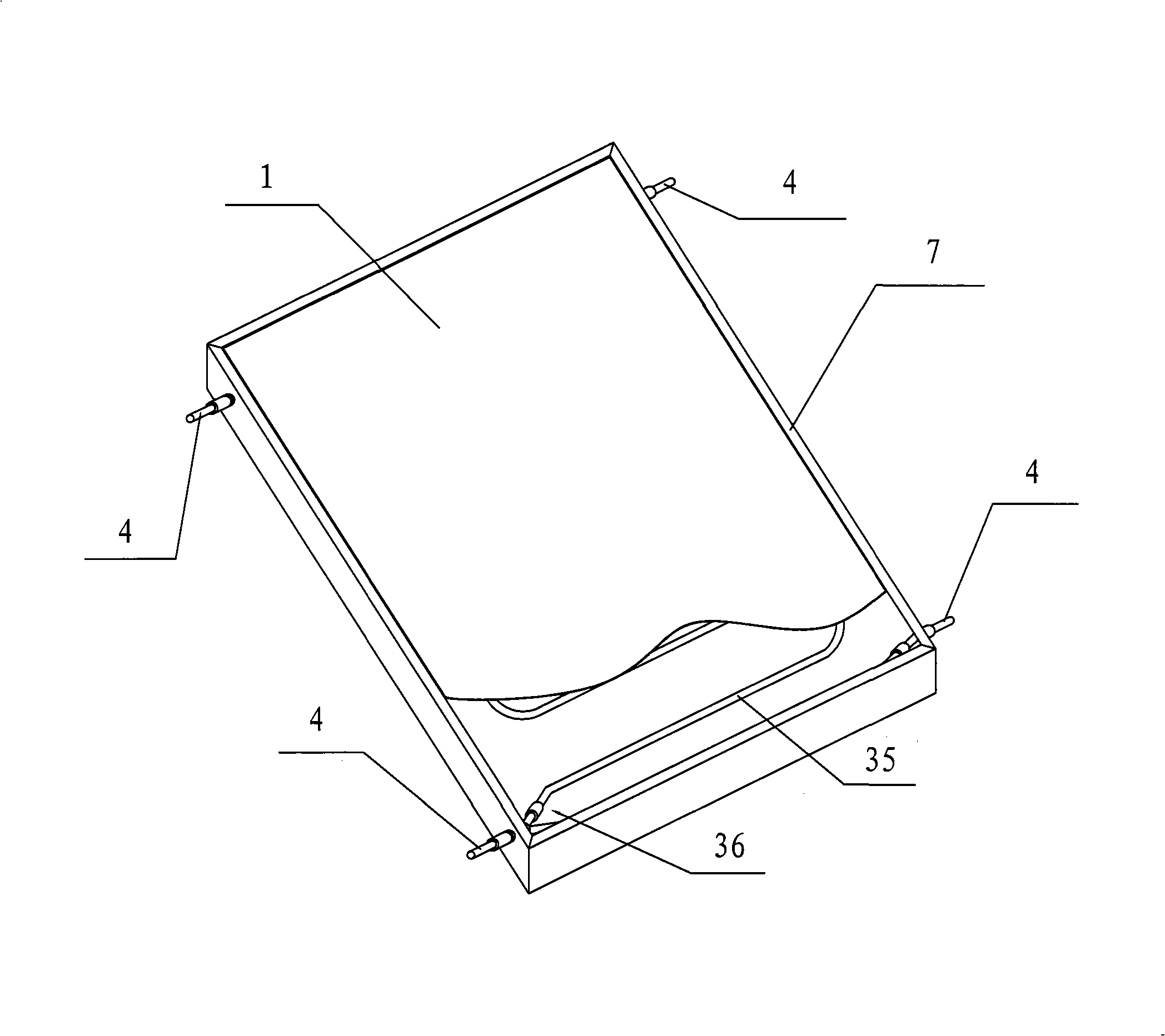
[0020] as attached figure 1 As shown, the flat-plate solar heat collector implemented according to the present invention includes a transparent cover plate 1 of glass, a heat collecting plate 2 made of aluminum, a tubular heat-conducting fluid channel 3, a bottom plate, and is used to connect the transparent cover plate 1, The heat collecting plate 2, the heat transfer fluid channel 3, the frame 7 fixed by the bottom plate, and the heat insulation cotton filled between the heat transfer fluid channel 3 and the bottom plate.

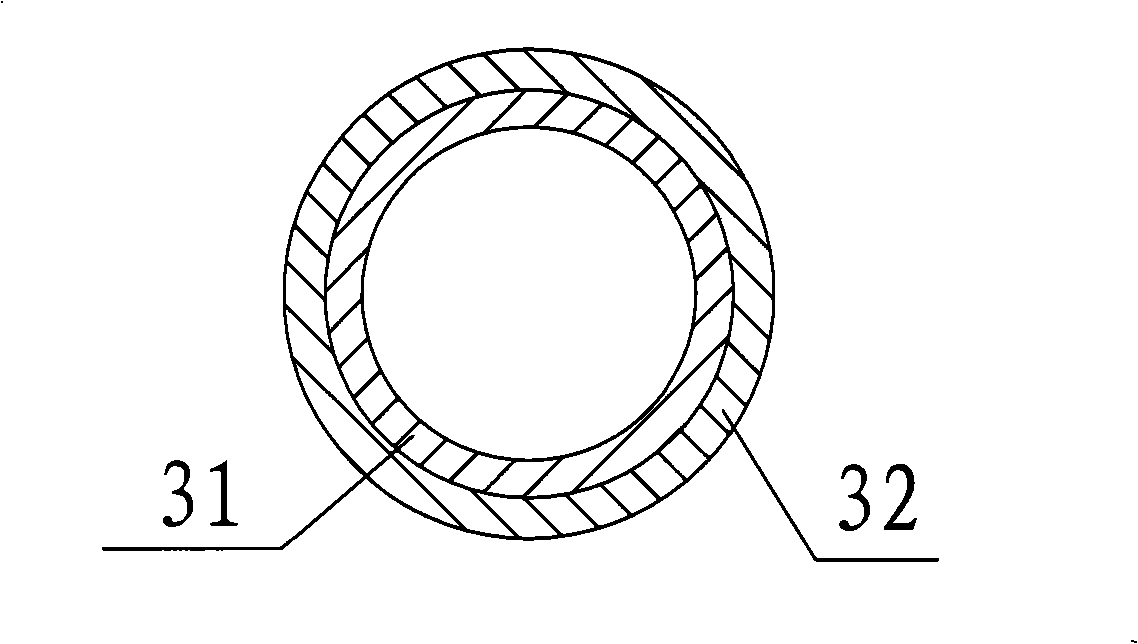
[0021] Wherein, the cross-sectional structure of the pipe fittings used in the heat transfer fluid channel 3 is as attached figure 2 As shown, it consists of an inner layer 31 made of copper and an outer layer 32 made of aluminum. And the heat conducting fluid channel 3 is welded to the lower surface of the heat collecting plate 2 .

[0022] A heat collecting film for absorbing heat energy is coated on the heat collecting plate 2 . The heat-collecting...

Embodiment 2

[0029] The difference between embodiment 2 and embodiment 1 is that the installation position of the fluid delivery pipe 4 is different, which is located on the other side of the heat collecting tube. Therefore as attached Image 6 As shown, during installation, the second end is directly connected to the fluid delivery pipe 4 , and the end of the extension pipe 41 is closed.

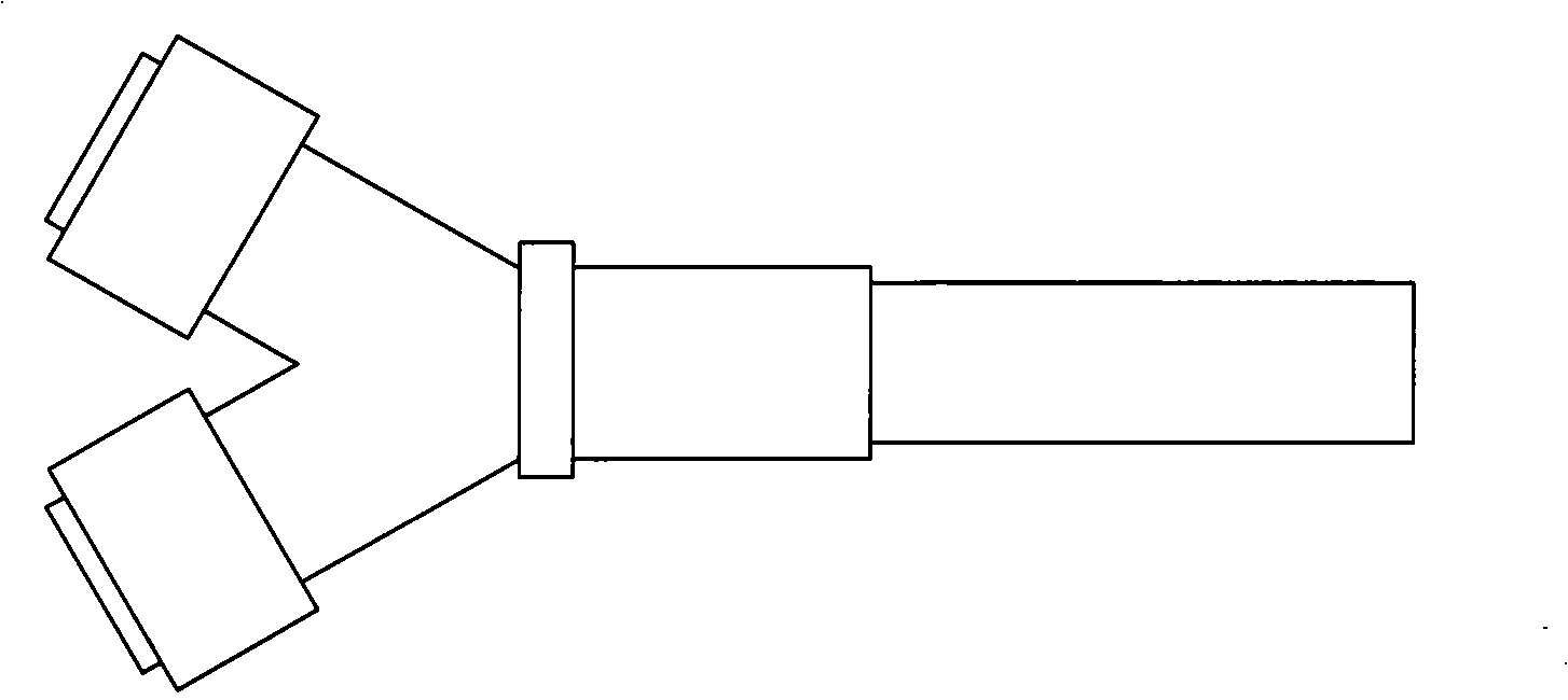
[0030] Since it is impossible to predict the arrangement position of the fluid delivery pipeline 4 during installation, it is impossible to determine from which side the fluid will flow into the serpentine pipe 35, so the three-way joint 36 is provided to facilitate installation and construction.

[0031] It is also possible to set tee joints 36 and extension pipes 41 at both ends of the fluid delivery pipeline 3, and reserve 4 pipeline joints on the 4 corners of the heat collector, so as to facilitate construction according to the position of the fluid delivery pipeline 4. Select the connector to be s...


PUM


Abstract

A plate form solar collector includes a light penetration cover plate, a collecting plate, a heat conduction fluid channel, heat insulating materials and a bottom plate stacked in turn, wherein the heat conduction fluid channel is a pipe fitting composed of an inner layer made of copper materials and aluminum materials. The use of the copper and aluminum composited tube greatly reduces the consumption of the copper materials, reduces the production cost. When the heat conduction fluid channel is welded at the bottom of the collecting plate, the copper aluminium weld is changed into the aluminium-aluminium weld, which reduces the welding difficulty and greatly reduces the investment cost of the welding device, and the aluminium-aluminium weld makes full use of the advantage of high thermal diffusivity of the aluminium metal, advances the conversion efficiency of the collecting plate solar. The collecting plate and the fluid channel are both made of aluminium with fast heat abstraction, wherein the inner layer is the copper material with high thermal conversion efficiency.

Description

technical field [0001] The invention relates to a flat-plate solar heat collector. Background technique [0002] With the implementation of the "Renewable Energy Law", my country has paid more and more attention to the utilization of renewable energy. Flat-plate solar collectors have the advantages of high heat collection efficiency, pressure-bearing separate installation, beautiful appearance, and can be used as building components to integrate with buildings, etc., and are rapidly occupying the domestic solar collector market. However, most of the flat-plate solar collectors in the prior art use pure copper tubes as the heat-conducting fluid passage, which is for anti-corrosion and prolonging the service life. However, the manufacturing cost of the copper tube is high, and since the heat collecting plate is an aluminum alloy sheet, it is difficult to weld with the copper tube. Contents of the invention [0003] The object of the present invention is to provide a flat-p...

Claims


Application Information

Patent Timeline
Patent Type & Authority Applications(China)
IPC IPC(8): F24J2/04F24J2/46F24J2/48
CPCY02E10/44F24J2/4654F24J2/4647F24J2/268F24S80/10F24S10/755F24S80/30
Inventor 吴俊田
Owner 吴俊田
Why Eureka
Try Eureka