Capacitance type touch control panel and manufacturing method thereof

A technology of capacitive touch and manufacturing method, which is applied in the direction of electric digital data processing, instrument, input/output process of data processing, etc., and can solve problems such as eye discomfort and visual fatigue

Inactive Publication Date: 2008-11-05
SHANTOU GOWORLD DISPLAY (PLANT II) CO LTD
View PDF0 Cites 15 Cited by
  • Summary
  • Abstract
  • Description
  • Claims
  • Application Information

AI Technical Summary

Problems solved by technology

[0005] In addition, linearly polarized light is easy to make the eyes feel uncomfortable and cause visual fatigue

Method used


Image

  • Capacitance type touch control panel and manufacturing method thereof
  • Capacitance type touch control panel and manufacturing method thereof
  • Capacitance type touch control panel and manufacturing method thereof

Examples


Embodiment 1

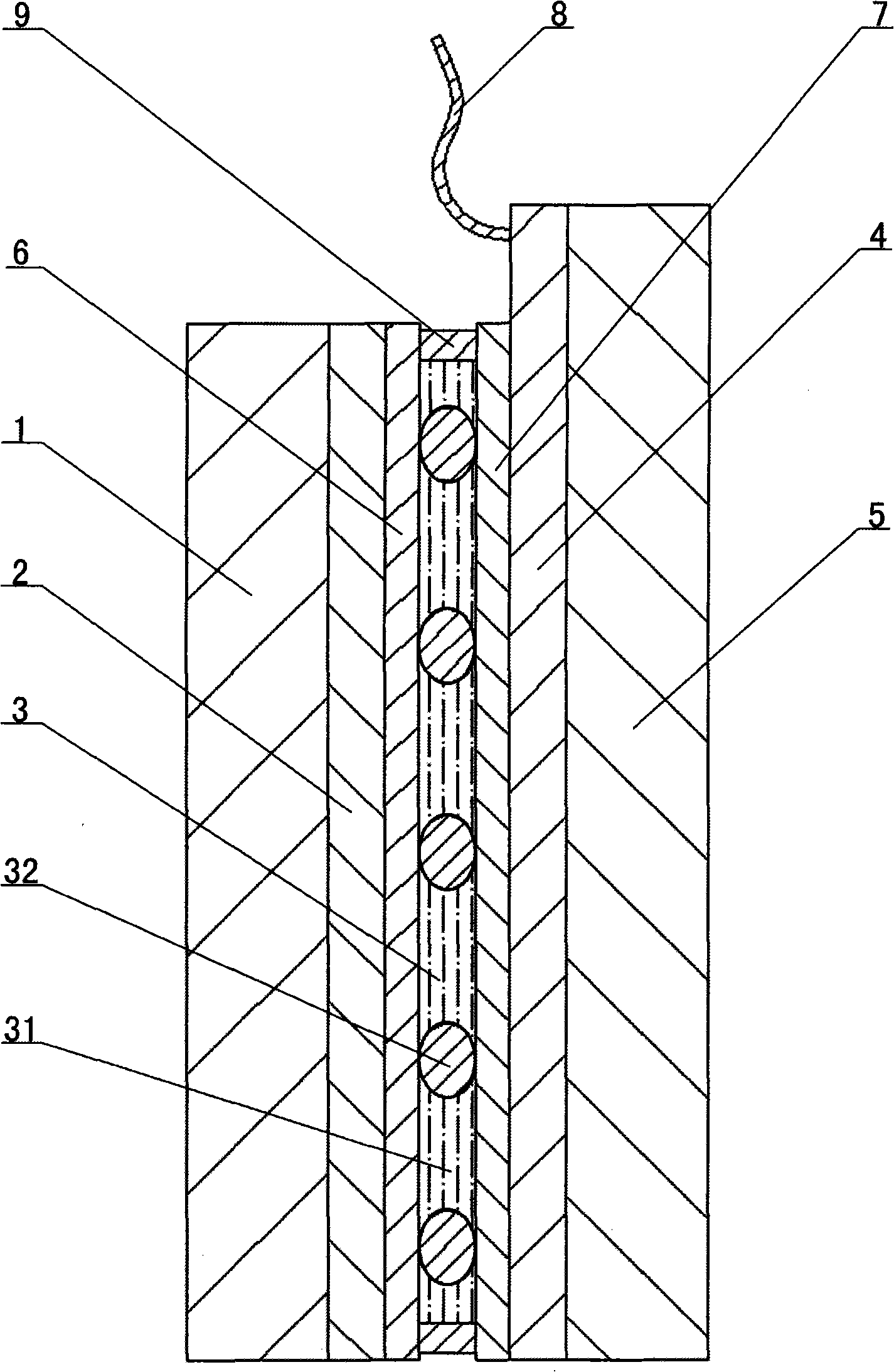
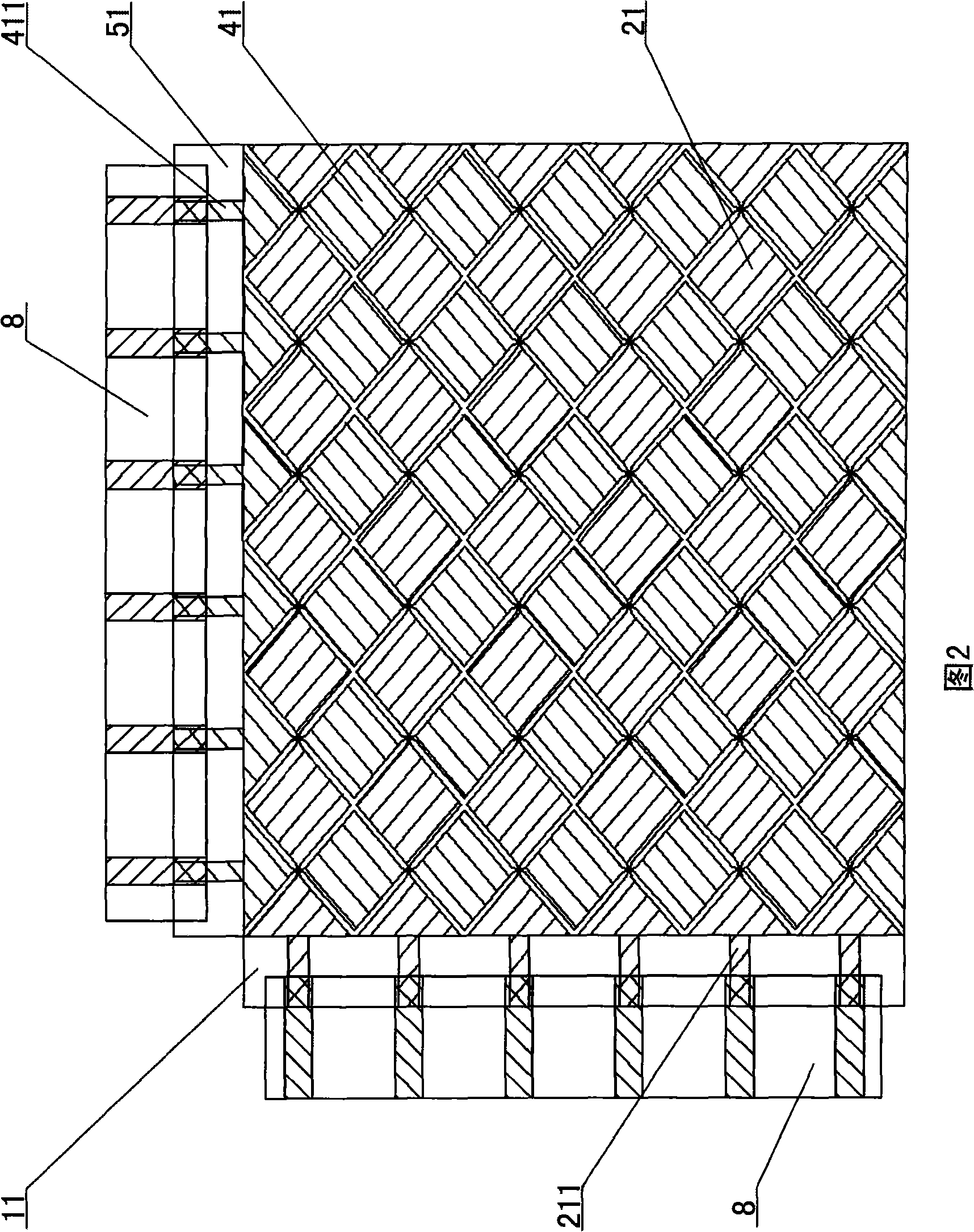
[0039] like figure 1 As shown in FIG. 2, this capacitive touch panel includes in order a first transparent insulating layer 1, a first transparent conductive material layer 2 containing an X-axis trace 21, a second transparent insulating layer 3, and a layer containing a Y-axis trace 41. The second transparent conductive material layer 4 and the third transparent insulating layer 5, the X-axis trace 21 has a first trace contact 211, and the Y-axis trace 41 has a second trace contact 411; the second transparent insulating layer 3 and the first transparent conductive material A first transparent alignment layer 6 is arranged between the layers 2, a second transparent alignment layer 7 is arranged between the second transparent insulating layer 3 and the second transparent conductive material layer 4; the second transparent insulating layer 3 is composed of liquid crystal 31, and the liquid crystal 31 is distributed with insulating particles (that is, the liquid crystal 31 is fil...

Embodiment 2

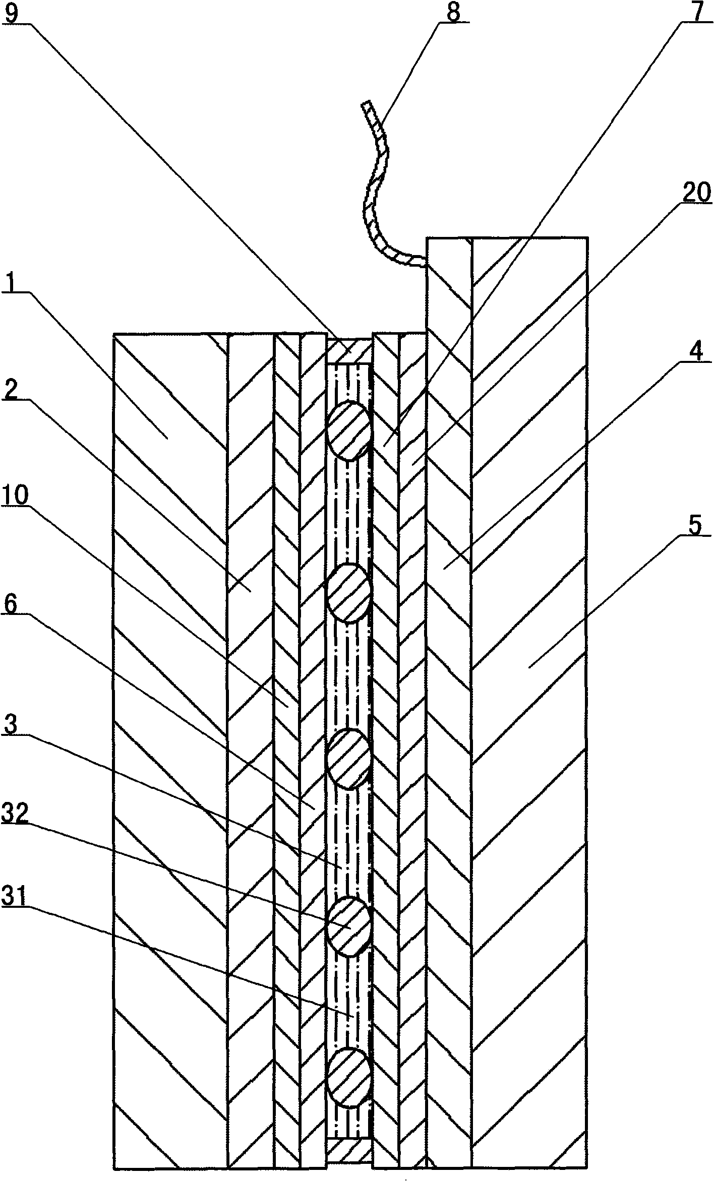
[0054] like image 3 As shown, a layer of transparent insulating material film layer 10 is arranged between the first transparent conductive material layer 2 and the first transparent alignment layer 6 of this capacitive touch panel, and the second transparent conductive material layer 4 and the second transparent alignment layer There is a layer of transparent insulating material film layer 20 between 7, and the transparent insulating material film layer 10 and the transparent insulating material film layer 20 are made of silicon carbide.

[0055] This capacitive touch panel is suitable for color liquid crystal display. The wavelength range of the emitted light of the color liquid crystal display is 380nm~780nm. The center wavelength λ=550nm can be selected as the basis for determining the optical path difference |Δn|d of the second transparent insulating layer , that is, the value of the optical path difference |Δn|d of the second transparent insulating layer. The optical pa...


PUM

PropertyMeasurementUnit
wavelengthaaaaaaaaaa

Abstract

A capacitor type touch control panel sequentially comprises a first transparent insulating layer which comprises an X axial core mark, a second transparent insulating layer, a second transparent conductive material layer which comprises a Y axial core mark, and a third transparent insulating layer. The X axial core mark is provided with a first core mark contact. The Y axial core mark is provided with a second core mark contact. The invention is characterized in that a first transparent oriented layer is provided between the second transparent insulating layer and the first transparent conductive material layer comprising the X axial core mark. A second transparent oriented layer is provided between the second transparent insulating layer and the second transparent conductive material layer comprising the Y axial core mark. The second transparent insulating layer is composed of liquid crystal. The invention also provides a method for preparing the capacitor type touch control panel. The invention can realize a two-dimensional locating function, and furthermore the second transparent insulating layer is equivalent to a wave plate. The linearly-polarized light which emits to the touch control panel can be leaded to become right circular polarized light or ellipse polarized light. The phenomenon of blind zone existing in some specific application occasions can be overcome.

Description

technical field [0001] The invention relates to an input device for human-machine interaction, in particular to a capacitive touch panel capable of realizing two-dimensional positioning and a manufacturing method thereof. Background technique [0002] At present, the touch panel is combined with a liquid crystal display as an input device, and is widely used in various electronic products, such as vehicle and ship products, public inquiry systems, household appliances, and various portable information terminal electronic products (such as high-end PDA (Personal Digital Assistant, personal digital assistant), smart phone, digital camera, game console, etc.). [0003] The light emitted by the liquid crystal display is usually linearly polarized light. Since the existing touch panel usually does not change the polarization state of the light, the light passing through the touch panel is still linearly polarized light, which has some problems in practical applications. [0004]...

Claims


Application Information

Patent Timeline
Patent Type & Authority Applications(China)
IPC IPC(8): G02F1/133G06F3/044
Inventor 陈伟川郑清交林铿吴永俊沈奕李永忠黄晓炀
Owner SHANTOU GOWORLD DISPLAY (PLANT II) CO LTD
Why Eureka
Try Eureka