Oscillating tooth reduction gear hub motor

A technology of in-wheel motor and movable tooth deceleration, applied in electrical components, electromechanical devices, electric components, etc., can solve the problems of low reliability, high noise, small reduction ratio range, etc. smooth effect

Inactive Publication Date: 2008-11-05
崔永兴
View PDF1 Cites 7 Cited by
  • Summary
  • Abstract
  • Description
  • Claims
  • Application Information

AI Technical Summary

Problems solved by technology

[0007] The purpose of the present invention is to overcome the disadvantages of the current high-speed hub motor with a reducer, such as large noise, small range of reduction ratio, limited motor speed, and low reliability, and provide a motor with a through-shaft structure and a reduction ratio of the reducer. The range is large (1.2 to 40, and the speed ratio of the reducer changes, which will not cause changes in the shape, position and space occupied by the reducer

Method used


Image

  • Oscillating tooth reduction gear hub motor
  • Oscillating tooth reduction gear hub motor
  • Oscillating tooth reduction gear hub motor

Examples


Embodiment Construction

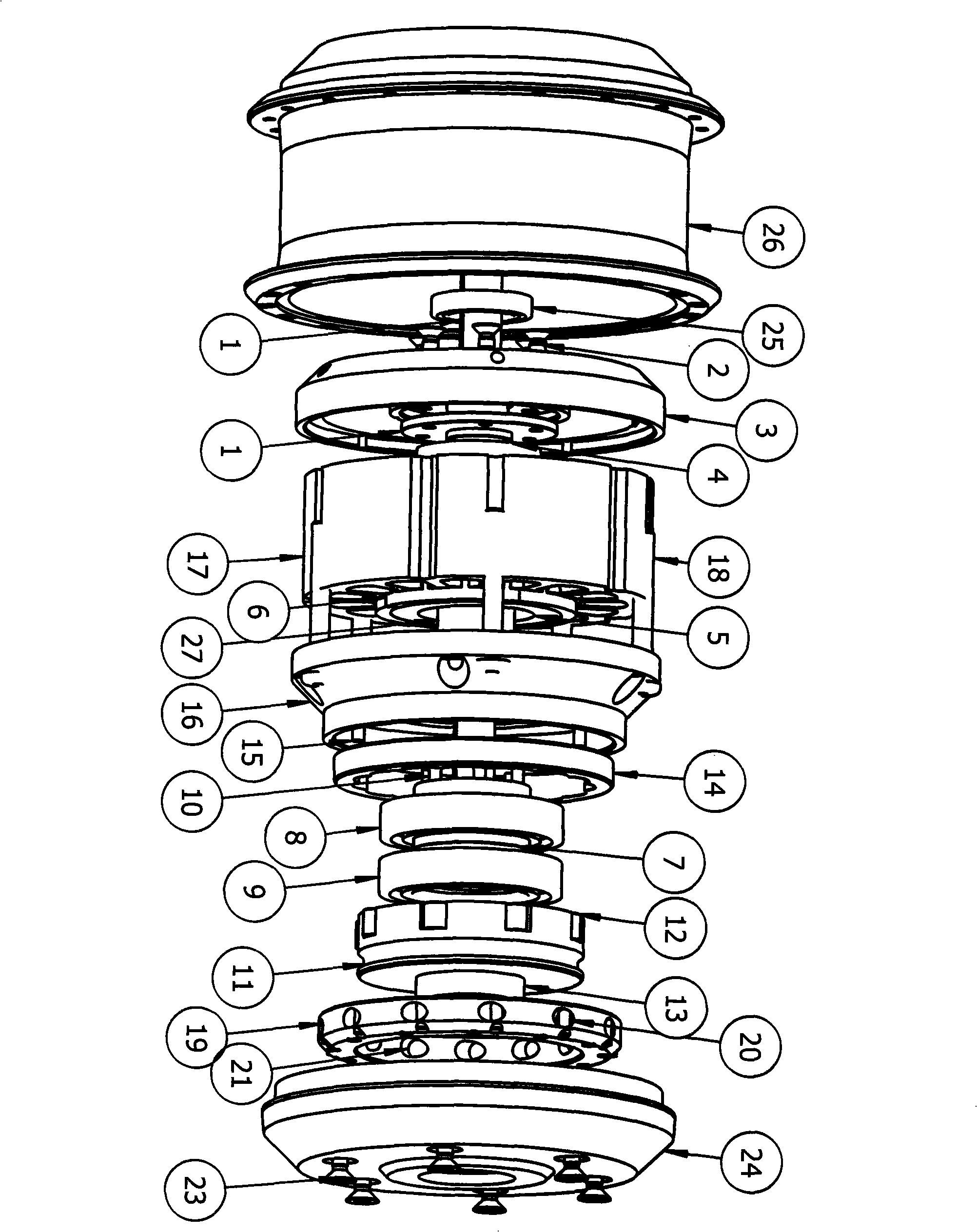
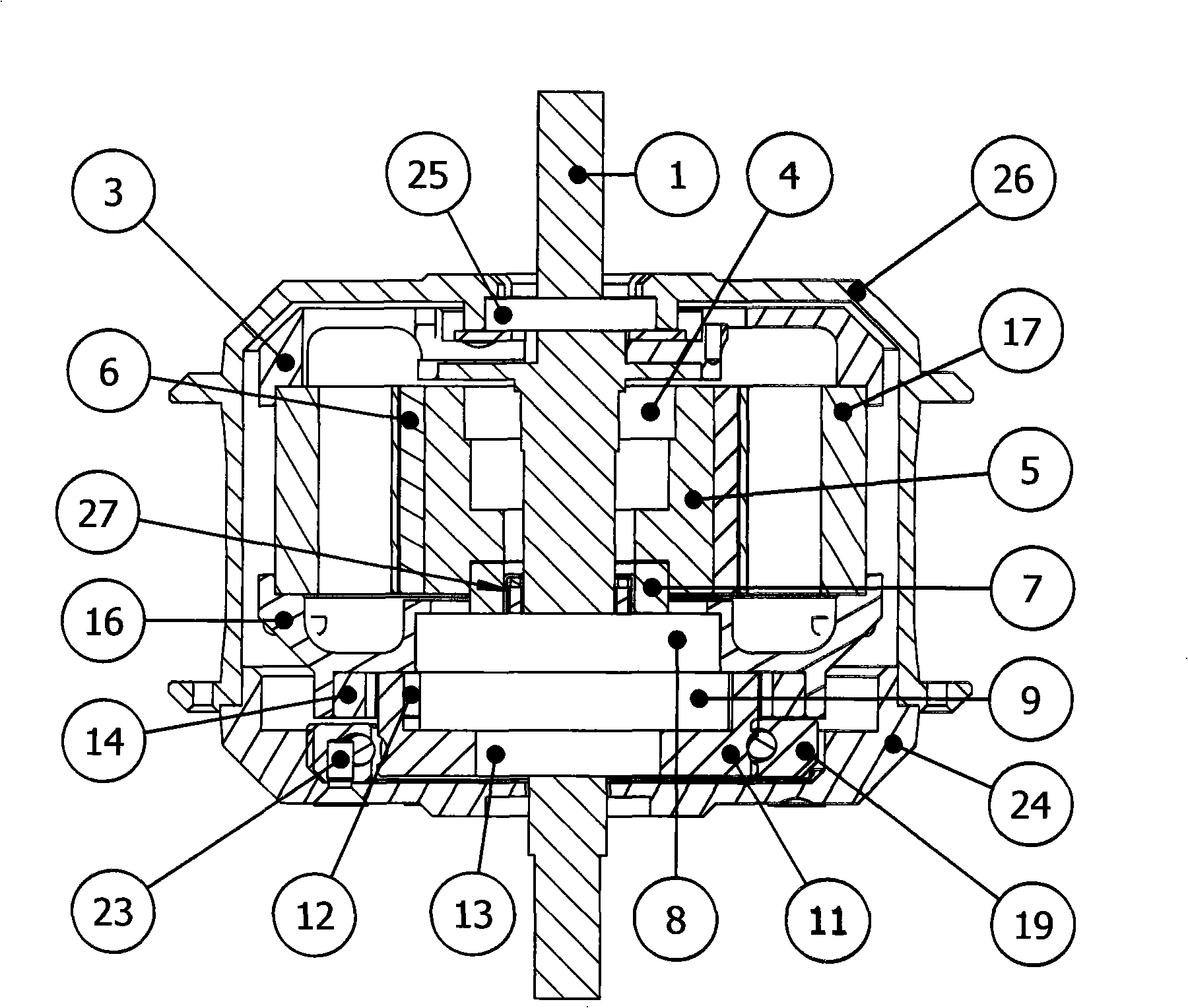
[0021] Depend on figure 1 Assemble the parts shown in the figure 2 The overall hub motor shown in the figure: connect the motor central shaft (1) and the left end cover of the stator (3) with the central shaft screw (2); connect the rotor (5) with the magnetic tile (6) through the rotor bearing (4) Assemble it into the central shaft (1) of the motor; press the supporting bearing (8) and the center wheel (14) into the right end cover (16) of the stator respectively, and fix the center wheel (14) with the fixed pin (15); The iron core stator (17) is inserted into the rotor (5), and the iron core stator (17) is clamped by the long screw (18) through the stator left end cover (3) and the stator right end cover (16); the inner hole of the eccentric shaft (7) and Needle roller bearings (27) are installed between the middle shafts (1) of the motor, and the eccentric shaft (7) equipped with the shock wheel (9) is installed and passed through the supporting bearing (8), and the rotor...


PUM


Abstract

An oscillating tooth reduction hub motor is characterized in that, a motor medial axis is connected with a stator left end cover, and the stator sleeved in the rotor through the left and the right stator end covers is wound by a long screw; the right stator end cover is provided with a center gear and an axial bearing; a needle bearing is arranged between the eccentric shaft and the medial axis provided with shock wave wheel with the outer ring assembled with passed through with axial bearing and butted with the stator; an oscillating tooth disc and a ball oscillating tooth are arranged between the shock wave wheel and the center gear; gears are arranged between the oscillating tooth disc and the medial axis; the ball channel at the outer ring of the oscillating tooth disc is loaded with a steel ball spring and a one-way bearing outer ring connected with the hub, thereby composing the one-way reduction hub motor with high speed input and low speed output. The oscillating tooth reduction hub motor of the invention advances the abrasion resistance of the reducer due to the adopted oscillating tooth reducer; reduces the volume, the weight and the materials by the high oscillating tooth and large speed ratio, wherein the efficiency, the torque and the current curve can be even smooth not to cause the curve to fluctuate in the large range because of the added load.

Description

Technical field: [0001] The invention relates to a geared motor, in particular to a high-speed hub motor decelerated by a movable tooth drive reducer. Background technique: [0002] The high-speed hub motor with reducer is used in electric vehicles, which is both the hub of the vehicle and the electric drive source of the vehicle. We know that the torque characteristics of low-speed hub motors are "soft". Electric vehicles using low-speed hub motors need to drive the motor with a large current when starting or climbing a slope. At this time, the efficiency of the motor will drop a lot. The high-speed motor has a wide high-efficiency platform. When the load is large, the efficiency of the high-speed motor is higher than that of the low-speed motor, and the reducer can increase the torque of the motor; the torque characteristic of the high-speed hub motor with a reducer is "hard". An electric vehicle using a high-speed hub motor with a reducer is significantly better than a l...

Claims


Application Information

Patent Timeline
IPC IPC(8): H02K7/116H02K5/22
Inventor 崔永兴
Owner 崔永兴
Why Eureka
Try Eureka