
Flux switching type axial magnetic field permanent magnet brushless motor

A permanent magnet brushless motor, axial magnetic field technology, applied in motors, electromechanical devices, electric vehicles, etc., can solve the problems of increasing the complexity of the rotor structure, irreversible demagnetization of permanent magnets, reducing the power density of the motor, etc. Responsive performance, small axial dimension, effect of improving dynamic performance

Inactive Publication Date: 2008-11-05
SOUTHEAST UNIV
View PDF0 Cites 31 Cited by
  • Summary
  • Abstract
  • Description
  • Claims
  • Application Information

AI Technical Summary

Problems solved by technology

Since this kind of motor places permanent magnets on the rotor, in order to overcome the centrifugal force at high speed, it is necessary to take special auxiliary measures for the rotor, such as installing fixtures made of stainless steel or non-metallic fiber materials, etc., which undoubtedly increases the speed of the rotor. The complexity of the structure also increases the manufacturing cost of the motor
At the same time, the permanent magnet is located in the rotor, the cooling condition is poor, and heat dissipation is difficult, and the high temperature rise may eventually lead to irreversible demagnetization of the permanent magnet, limit the output of the motor, reduce the power density of the motor, etc., restricting the further improvement of the performance of the motor
[0003] The flux-switching permanent magnet motor proposed by the French scholar E.Hoang, the motor places the permanent magnet on the stator, so that the structure of the rotor is simple, and there is neither winding nor permanent magnet on the rotor, which avoids the above problems, but This motor is a radial magnetic field motor, which is not suitable for occasions that strictly require thin installation. The single air gap structure makes the motor power density low

Method used


Image

  • Flux switching type axial magnetic field permanent magnet brushless motor
  • Flux switching type axial magnetic field permanent magnet brushless motor

Examples


Embodiment Construction

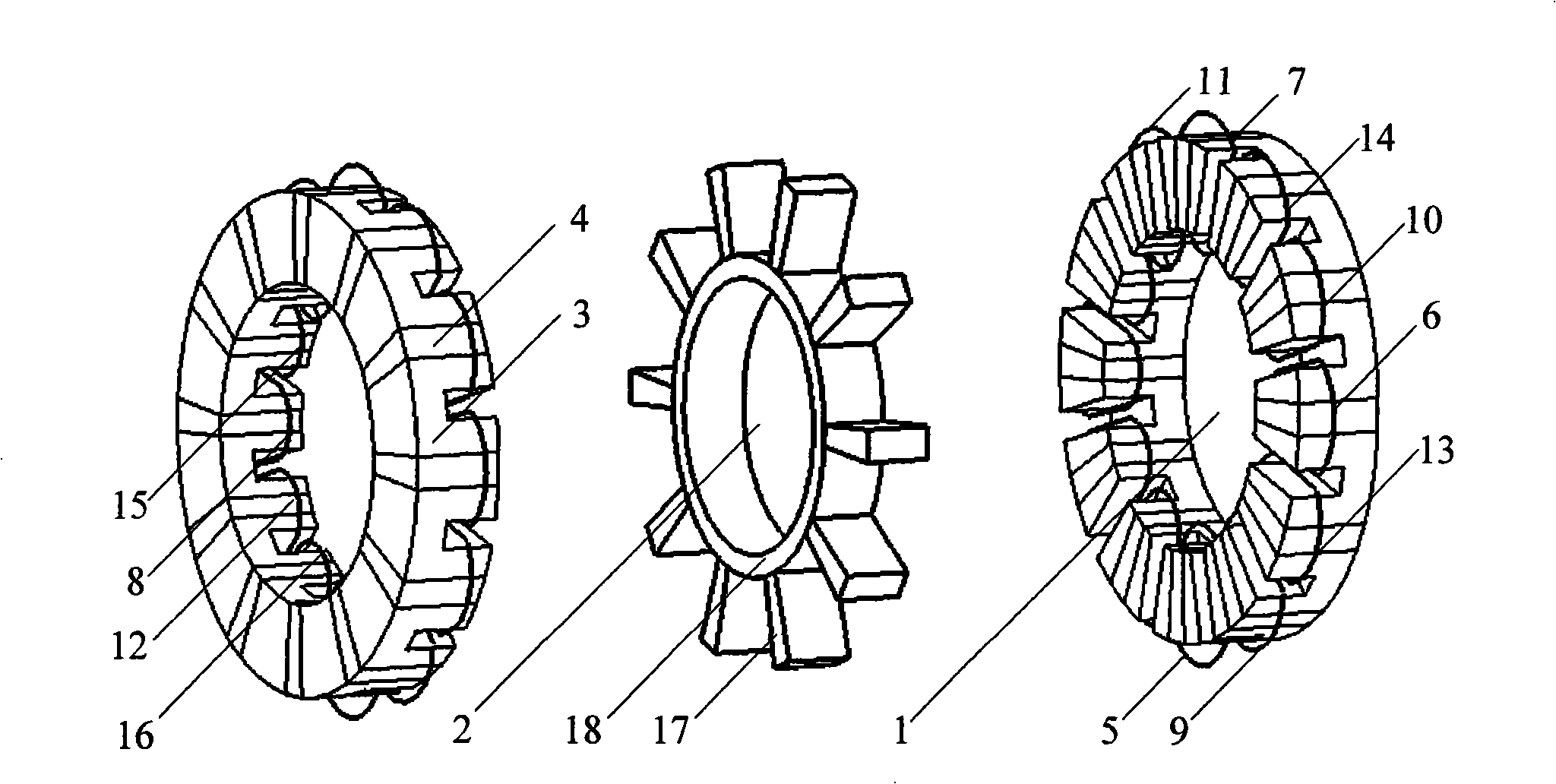
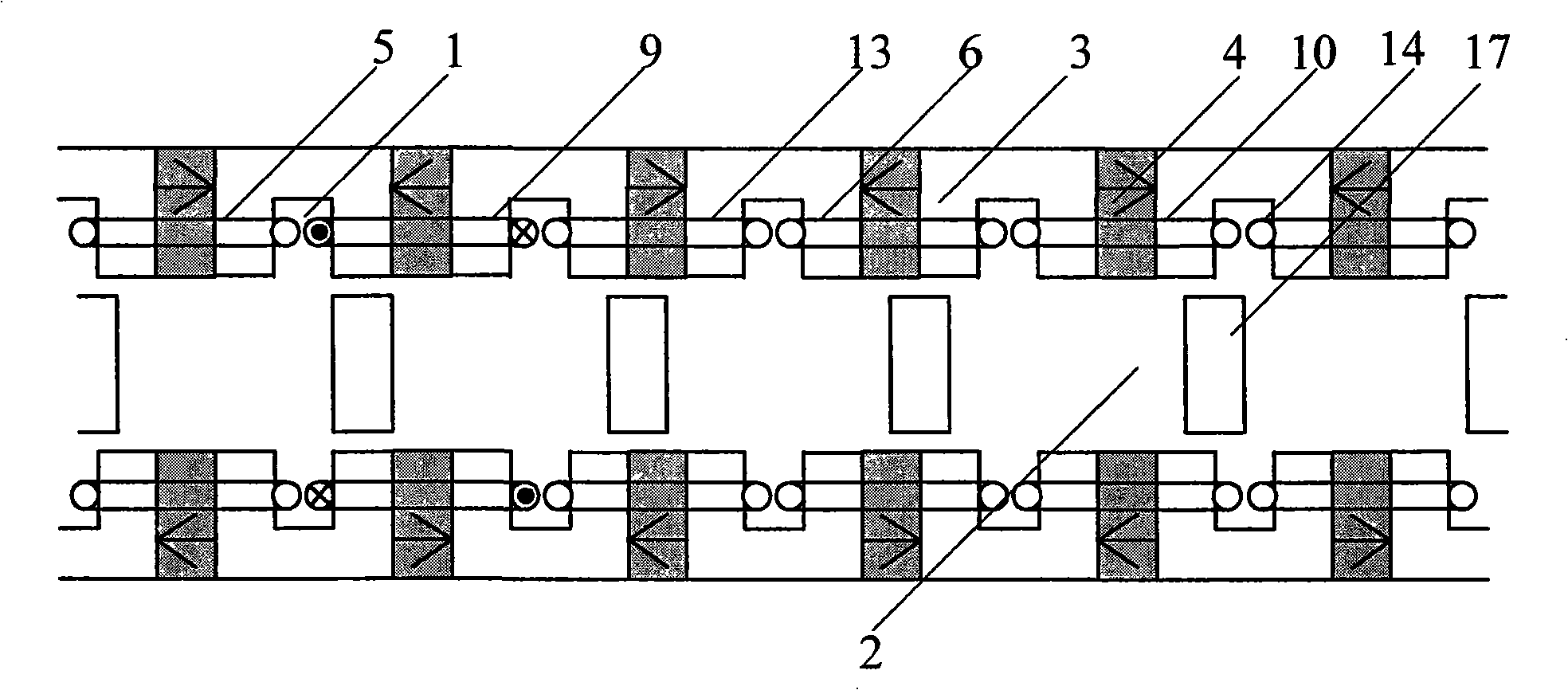
[0011] The motor consists of 6 U-shaped stator cores 3 and 6 permanent magnets 4. The stator 1 and 5 rotor poles 17 are combined into a basic motor with a 6 / 5 structure. The stator 1 and rotor poles 17 of the basic motor are integer multiples. By extension, a motor with a structure of 6a / 5a can be obtained, where a is a positive integer.

[0012] Such as figure 1 As shown, the flux-switching axial field permanent magnet brushless motor is a double-air-gap permanent magnet motor composed of two stators 1 and a rotor 2. The stator 1 and the rotor 2 are coaxially installed, and the rotor 2 is sandwiched between two There is an air gap of a certain thickness between the stators 1 and between the rotor 2 and the stator 1 . The structures of the two stators 1 are exactly the same, and they are symmetrical about the rotor 2; each stator 1 is composed of 12 U-shaped stator cores 3, 12 sector-shaped permanent magnets 4 and 12 concentrated windings 5, and the U-shaped stator core 3 an...


PUM


Abstract

A magnetic flux switch type axial magnetic field permanent magnet brushless machine relates to a double air gap permanent magnet machine composed of two stators (1) and a rotor (2), wherein the stators (1) and a rotor (2) are arranged axially; the rotor (2) is clamped between two stators (1); the air gap with certain thickness is arranged between the stator (1) and the rotor (2); each stator (1) is composed of 12 U-shaped stator cores (3), 12 sector permanent magnets (4) and 12 coil2 (5); the U-shaped stator cores (3) and the sector permanent magnets (4) are put alternately to constitute the disc; the U-shaped stator core (3) and the permanent magnet (4) are respectively corresponding on the two stators (1), but the magnetizing directions of the two corresponding permanent magnets are opposite. The simple structure advances the operation reliability and the dynamic performance of the motor, meanwhile the axial size is smaller, which is suitable for the place requiring the thin mount, such as the robot, the computer peripherals, the electric automobiles and the wind electric power generation and the like.

Description

technical field [0001] The invention relates to a magnetic flux switching type axial magnetic field permanent magnet brushless motor, which is an improvement to the traditional axial magnetic field permanent magnet brushless motor and belongs to the technical field of permanent magnet motors. Background technique [0002] The traditional axial magnetic field permanent magnet brushless motor adopts a slotless structure with a small magnetic load, while a slotted structure has a higher power density but is difficult to manufacture and requires special equipment. Regardless of whether it is a single air gap or double air gap axial field permanent magnet brushless motor, the rotor is composed of high performance permanent magnet materials bonded to solid steel or silicon steel sheets. Since this kind of motor places permanent magnets on the rotor, in order to overcome the centrifugal force during high-speed operation, it is necessary to take special auxiliary measures for the ro...

Claims


Application Information

Patent Timeline
IPC IPC(8): H02K16/04H02K1/17H02K15/02
CPCY02T10/641Y02T10/64
Inventor 林明耀诸自强
Owner SOUTHEAST UNIV
Features
  • Generate Ideas
  • Intellectual Property
  • Life Sciences
  • Materials
  • Tech Scout
  • Unparalleled Data Quality
  • Higher Quality Content
  • 60% Fewer Hallucinations
Learn More