Method and apparatus system for compensating temperature of power amplifier

A temperature compensation device and power amplifier technology, applied in the electronic field, can solve the problems of high production cost, poor anti-interference, poor temperature accuracy, etc., and achieve the effects of reduced production cost, enhanced anti-interference, and improved temperature compensation accuracy

Inactive Publication Date: 2008-11-05
NTS TECH CHENGDU
View PDF0 Cites 14 Cited by
  • Summary
  • Abstract
  • Description
  • Claims
  • Application Information

AI Technical Summary

Problems solved by technology

[0009] The purpose of the present invention is to: solve the temperature compensation of each LDMOS power amplifier tube in the prior art based on the same, fixed temperature compensation data table, use an analog temperature sensor to detect the poor temperature accuracy of the power amplifier tube, and other problems The common reference voltage circuit of the circuit causes the problems of low temperature compensation accuracy, poor anti-interference performance and high production cost for LDMOS power amplifier tubes; it provides a method that uses a digital temperature sensor to detect the temperature of the power amplifier tube and automatically calculates the temperature of each power amplifier tube to be tested. Corresponding temperature compensation data, and using a separate reference voltage module to provide a reference voltage for the D / A conversion module, a power amplifier temperature compensation method and device system with high temperature compensation accuracy and strong anti-interference

Method used


Image

  • Method and apparatus system for compensating temperature of power amplifier
  • Method and apparatus system for compensating temperature of power amplifier
  • Method and apparatus system for compensating temperature of power amplifier

Examples


Embodiment Construction

[0051] In order to make the object, technical solution and advantages of the present invention clearer, the present invention will be further described in detail below in conjunction with the accompanying drawings and embodiments. It should be understood that the specific embodiments described here are only used to explain the present invention, not to limit the present invention.

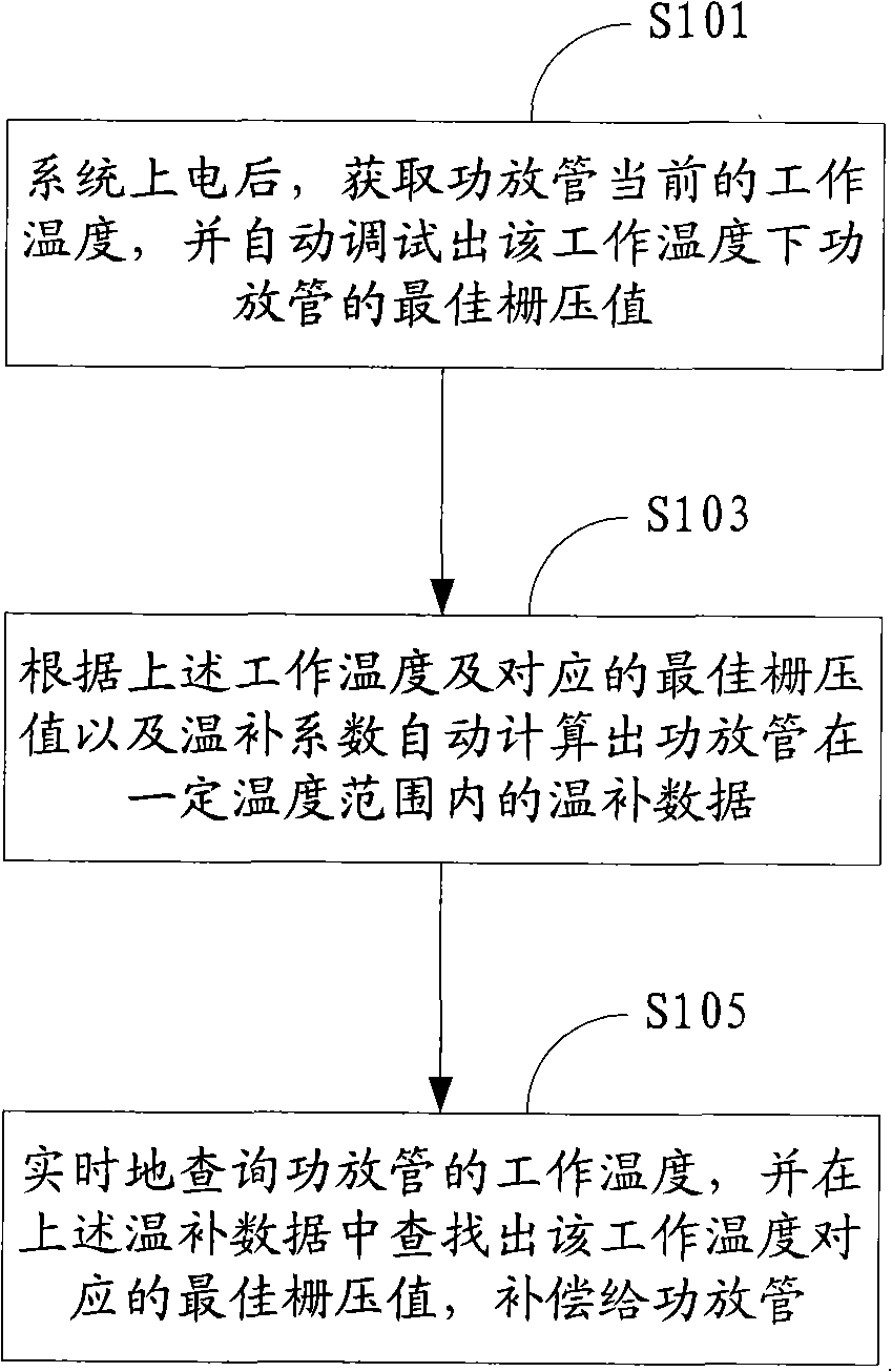
[0052] The power amplifier temperature compensation method and device system provided by the embodiments of the present invention detect the working temperature of the LDMOS power amplifier tube in real time, and provide the best grid voltage value for the LDMOS power amplifier tube according to the working temperature, so that the LDMOS power amplifier tube can be operated at any time. It works at the best communication power amplifier operating point under the temperature.

[0053] figure 1 The implementation flow of the power amplifier temperature compensation method provided by the embodiment ...


PUM


Abstract

The invention is suitable for the electronic technology field, which provides a power amplifier temperature compensation method and a device system, wherein the method includes obtaining the current working temperature of the temperature compensated power tube, automatically adjusting the optimum grid voltage of the power tube under the current working temperature; computing the warming and invigouating data in a certain range according to the current working temperature and the optimum grid voltage; real-time detecting the working temperature of the power tube, looking for the corresponding offset data in the warming and invigouating data according to the working temperature, and performing the temperature compensation to the power tube by the offset data. The invention automatically matches the corresponding warming and invigouating data for the power tubes required for temperature compensation, and obtains the temperature information of the power tube through the digital temperature sensor, and adopts the separate reference voltage module to provide the reference voltage for the D/A modular converter, which advances the temperature compensation precision of the LDMOS power tube and enhances the interference immunity.

Description

Technical field [0001] The invention belongs to the field of electronic technology, and in particular relates to a power amplifier temperature compensation method and device system. Background technique [0002] The static operating current of the LDMOS power amplifier tube directly affects the performance of the power amplifier tube. Providing different grid voltages to the power amplifier tube can obtain different static operating currents. As the ambient temperature changes, if the grid voltage of the power amplifier tube remains unchanged, the power amplifier The quiescent operating current of the tube will drift, causing the performance of the power amplifier tube to deteriorate. [0003] On the one hand, the turn-on voltage of the field effect transistor becomes smaller with the increase of temperature. On the other hand, the electron mobility becomes smaller with the increase of temperature. These two aspects influence each other, making the static state of the field ...

Claims


Application Information

Patent Timeline
Patent Type & Authority Applications(China)
IPC IPC(8): H03F1/30
Inventor 刘键程勇其
Owner NTS TECH CHENGDU
Why Eureka
Try Eureka