Radio frequency module and communication device

a radio frequency module and communication device technology, applied in the direction of rf amplifiers, high frequency amplifiers, low noise amplifiers, etc., can solve the problem of difficulty in high accuracy temperature compensation, achieve the effect of improving the accuracy of temperature compensation suppressing gain fluctuations in the first amplifier circuit caused by temperature changes, and enhancing the linearity of the first amplifier circuit amplification characteristics

Active Publication Date: 2019-07-09
MURATA MFG CO LTD
View PDF7 Cites 0 Cited by
  • Summary
  • Abstract
  • Description
  • Claims
  • Application Information

AI Technical Summary

Benefits of technology

[0014]According to this configuration, substantially the same temperature compensation as in the related art can be performed in the first amplifier circuit. In addition, because the component having the heat generating property lower than that of the second amplifier circuit is arranged between the first and second areas, the influence of the heat from the second amplifier circuit on the first amplifier circuit is reduced, and the accuracy of the temperature compensation in the first amplifier circuit is improved.
[0025]According to this configuration, the influence of the heat from the second amplifier circuit on the first diode and the influence of the heat from the second amplifier circuit on the second diode are similar to each other. Thus the temperature difference between the first and second diodes is reduced, and the accuracy of the temperature compensation is improved.

Problems solved by technology

However, when the module including the plurality of amplifier circuits simply applies the related art to each of the amplifier circuits, a temperature-characteristics compensation circuit is affected by the heat generated in the other amplifier circuits, and it is difficult to perform temperature compensation with high accuracy.

Method used


Image

  • Radio frequency module and communication device
  • Radio frequency module and communication device
  • Radio frequency module and communication device

Examples


first embodiment

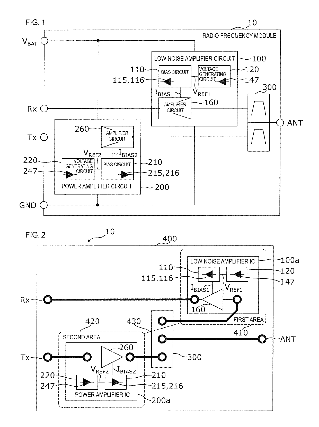
[0037]An example radio frequency module according to a first embodiment may be a composite component for use on a front end of a communication device and include a low-noise amplifier circuit configured to amplify a reception signal of a radio frequency and a power amplifier circuit configured to amplify a transmission signal of a radio frequency, both of the circuits being implemented on a single substrate.

[0038]FIG. 1 is a block diagram that illustrates an example of a functional configuration of the radio frequency module according to the first embodiment. As illustrated in FIG. 1, a radio frequency module 10 includes a low-noise amplifier circuit 100, a power amplifier circuit 200, and a duplexer 300.

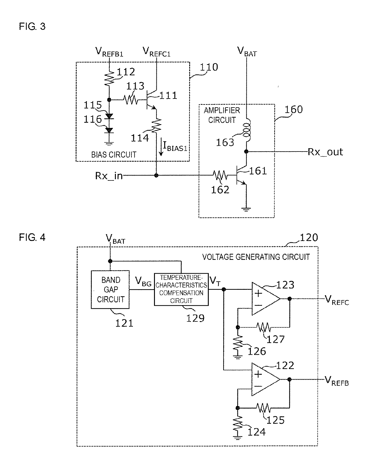
[0039]The low-noise amplifier circuit 100 is an amplifier circuit with the temperature compensation function and is configured to amplify a reception signal received from the duplexer 300 and transmit it to an Rx terminal. The low-noise amplifier circuit 100 includes a bias circuit ...

second embodiment

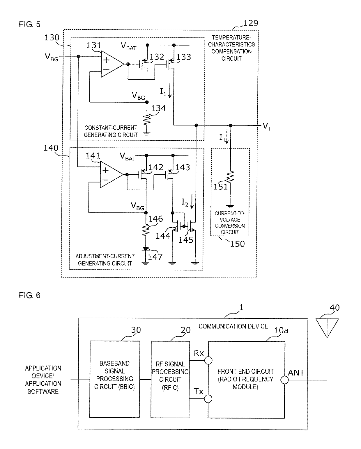
[0082]A communication device including the radio frequency module according to the first embodiment is described in a second embodiment.

[0083]FIG. 6 is a block diagram that illustrates an example of a functional configuration of a communication device 1 according to the second embodiment. As illustrated in FIG. 6, the communication device 1 includes a front-end circuit 10a, an RF signal processing circuit 20, and a baseband signal processing circuit 30.

[0084]The front-end circuit 10a is configured to amplify a transmission RF signal generated by the RF signal processing circuit 20 by using a power amplifier and to supply it to an antenna 40. The front-end circuit 10a is also configured to amplify a reception RF signal received at the antenna 40 by using a low-noise amplifier and to supply it to the RF signal processing circuit 20. The front-end circuit 10a includes the radio frequency module 10 according to the first embodiment.

[0085]The RF signal processing circuit 20 is configured...


PUM


Abstract

A radio-frequency module includes a substrate, a low-noise amplifier circuit being a first amplifier circuit arranged in a first area in the substrate, a power amplifier circuit being a second amplifier circuit arranged in a second area in the substrate, and a duplexer being a component arranged between the first area and the second area in the substrate and having a heat generating property lower than that of the power amplifier circuit. The low-noise amplifier circuit includes a bias circuit configured to generate a bias current dependent on temperature characteristics of a first diode, a voltage generating circuit configured to generate a voltage dependent on temperature characteristics of a second diode as an operating voltage for the bias circuit, and an amplifier circuit configured to operate at an operating point determined by the bias current.

Description

[0001]This application claims priority from Japanese Patent Application No. 2016-236330 filed on Dec. 6, 2016. The content of this application is incorporated herein by reference in its entirety.BACKGROUND OF THE DISCLOSURE1. Field of the Disclosure[0002]The present disclosure relates to a radio frequency module and a communication device.2. Description of the Related Art[0003]Power amplifying modules for amplifying transmission signals of radio frequencies are used in various communication devices, such as wireless terminal devices (see, for example, Japanese Unexamined Patent Application Publication No. 2014-171170).[0004]The above-mentioned patent document discloses a first power amplifying module. This module includes a constant voltage generating circuit for generating a constant voltage independent of a power supply voltage, a bias circuit for generating a bias current by using the constant voltage as an operating voltage, and an amplifying circuit for amplifying a transmissio...

Claims


Application Information

Patent Timeline
Patent Type & Authority Patents(United States)
IPC IPC(8): H03F3/04H03F3/24H03F3/213H03F1/02H03F3/195H03F1/30
CPCH03F1/302H03F1/0205H03F1/0261H03F3/195H03F3/213H03F3/245H03F2200/555H03F2200/18H03F2200/294H03F2200/447H03F2200/451H03F1/301H03F3/19H03F3/21
Inventor YOSHIZAKI, YASUNOBU
Owner MURATA MFG CO LTD
Why Eureka
Try Eureka