Circuit device, oscillator, electronic apparatus, and vehicle

a technology of circuit devices and electronic equipment, applied in the direction of oscillator stabilization, electrical equipment, oscillator generators, etc., can solve the problems of power source noise in some cases, difficulty in providing inter-power supply capacitors in some cases, and inability to accurately measure parameters. , to achieve the effect of improving the accuracy of temperature compensation and reducing the error of measurement of parameters

Active Publication Date: 2019-11-26
SEIKO EPSON CORP
View PDF14 Cites 0 Cited by
  • Summary
  • Abstract
  • Description
  • Claims
  • Application Information

AI Technical Summary

Benefits of technology

[0005]An advantage of some aspects of the invention is to provide a circuit device, an oscillator, an electronic apparatus, a vehicle, and the like capable of reducing an error in measurement of a parameter used in temperature compensation to improve the accuracy of the temperature compensation.
[0008]According to the aspect of the invention, the inter-power-supply capacitor is formed of at least two metal layers provided in the region where the temperature compensation circuit is disposed. That is, the inter-power-supply capacitor is formed in the circuit device. The impedance of the power supply lines is therefore unlikely to be affected by the environment outside the circuit device, whereby decrease in accuracy of the temperature compensation resulting from a difference between the measurement / inspection environment and the implementation environment can be reduced. As a result, an error in measurement of a parameter used in the temperature compensation can be reduced for improvement in the accuracy of the temperature compensation.
[0012]Although the inter-power-supply capacitor needs to have large capacitance, it is difficult in some cases for an electrode having a two-layer structure for forming the inter-power-supply capacitor to achieve the required capacitance in a semiconductor chip because the area of the semiconductor chip is limited. In this regard, in the aspect of the invention, the i-th metal layer and the (i−1)-th and (i+1)-th metal layers above and below the i-th metal layer can be used to form the first and second capacitors in the same region. As a result, the capacitance of the inter-power-supply capacitor can be increased, whereby the accuracy of the temperature compensation can be further improved.
[0016]Providing the second inter-power-supply capacitor in any of the pad disposition regions as described above allows effective use of a vacant portion of the pad disposition region for increase in the capacitance of the inter-power-supply capacitor and hence improvement in the function as a bypass capacitor. The accuracy of the temperature compensation is therefore likely to be further improved. Further, as will be described later, removing the pad disposition regions but leaving a circuit disposition region allows creation of a shrunk-version layout having a decreased layout area, as will be described later. In this case, the second inter-power-supply capacitor is omitted, but the inter-power-supply capacitor provided in the region where the temperature compensation circuit is disposed reduces decrease in the accuracy of the temperature compensation also in the shrunk-version layout.
[0022]Since the reference voltage is supplied to the temperature compensation circuit, the quality of the reference voltage (amount of noise and accuracy of voltage, for example) affects the accuracy of the temperature compensation. In this regard, according to the aspect of the invention, since the resistive element (polysilicon) that forms the reference voltage generation circuit is formed on the well to which the low-potential-side power supply voltage is applied, the amount of noise contained in the reference voltage can be reduced. The decrease in the accuracy of the temperature compensation due to the difference in the power supply environment can therefore be further reduced.

Problems solved by technology

A difference between the environment in which the measurement and inspection are performed and the environment in which the oscillator is implemented in the product is likely to cause an error between the parameter obtained in the environment in which the measurement and inspection are performed and a parameter appropriate for the environment in which the oscillator is implemented in the product.
The accuracy of temperature compensation in the environment in which the oscillator is implemented in the product is therefore likely to decrease.
Although the inter-power-supply capacitor needs to have large capacitance, it is difficult in some cases for an electrode having a two-layer structure for forming the inter-power-supply capacitor to achieve the required capacitance in a semiconductor chip because the area of the semiconductor chip is limited.
It is therefore difficult in some cases to provide an inter-power-supply capacitor having necessary large capacitance in the region where the oscillation circuit is disposed.
Further, the oscillation signal produced by the oscillation circuit may be coupled to the inter-power-supply capacitor, undesirably resulting in power source noise in some cases.
Further, it can be expected that the amount of coupling-induced power supply noise from the temperature compensation circuit is smaller than the amount of power supply noise from the oscillation circuit.
In this case, the second inter-power-supply capacitor is omitted, but the inter-power-supply capacitor provided in the region where the temperature compensation circuit is disposed reduces decrease in the accuracy of the temperature compensation also in the shrunk-version layout.
Since the reference voltage is supplied to the temperature compensation circuit, the quality of the reference voltage (amount of noise and accuracy of voltage, for example) affects the accuracy of the temperature compensation.

Method used


Image

  • Circuit device, oscillator, electronic apparatus, and vehicle
  • Circuit device, oscillator, electronic apparatus, and vehicle
  • Circuit device, oscillator, electronic apparatus, and vehicle

Examples


Embodiment Construction

[0044]A preferable embodiment of the invention will be described below in detail. It is not intended that the present embodiment described below unduly limits the contents of the invention set forth in the appended claims, and all configurations described in the present embodiment are not necessarily essential as a solution provided by the invention.

1. Circuit Device

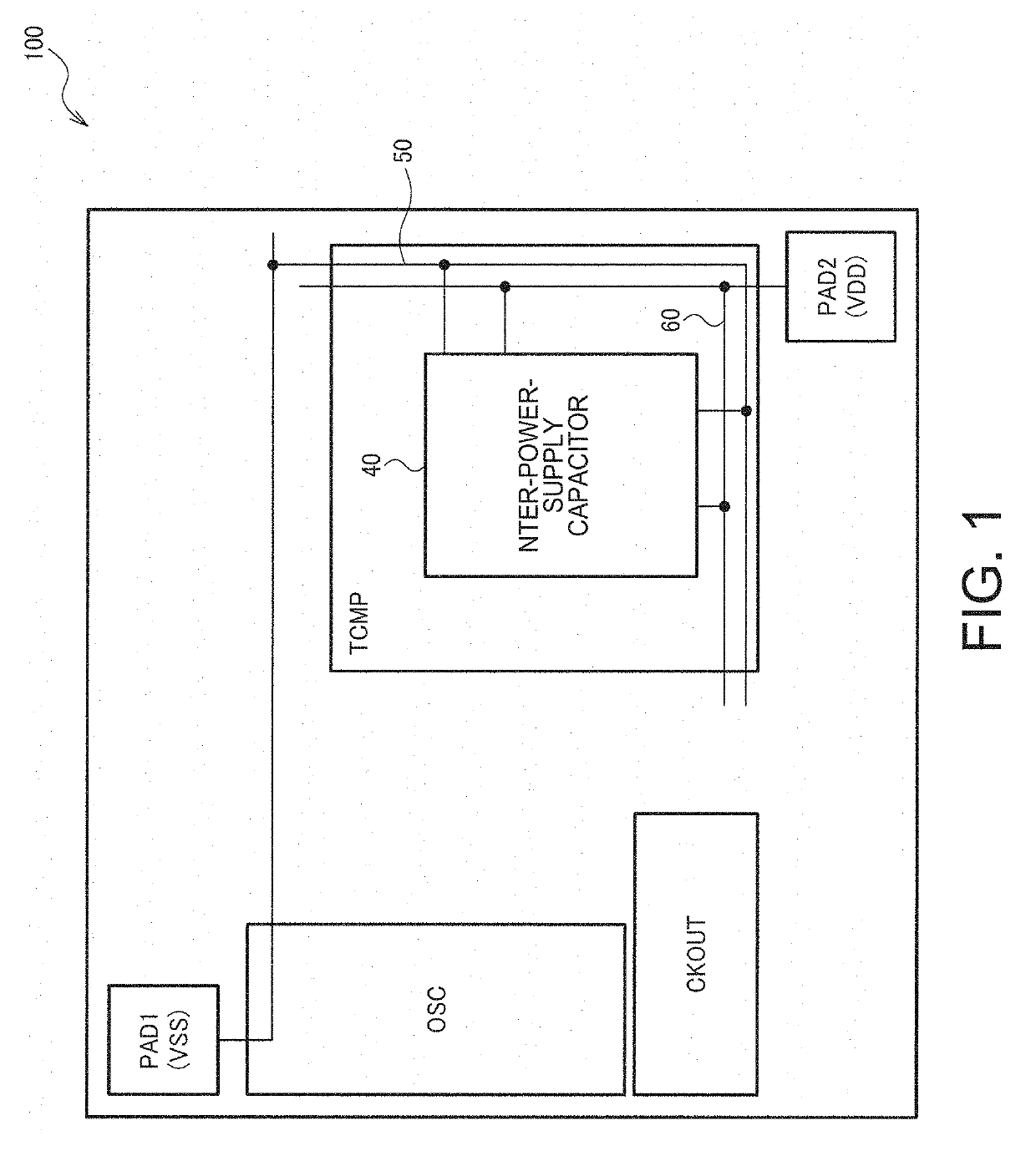
[0045]FIG. 1 shows an example of the layout configuration of a circuit device 100 according to the present embodiment. The circuit device 100 includes an oscillation circuit, a clock signal output circuit, a temperature compensation circuit, a low-potential-side power supply pad (first pad), a high-potential-side power supply pad (second pad), and an inter-power-supply capacitor 40. It is noted that the present embodiment is not limited to the configuration in FIG. 1, and that part of the components in the configuration can be omitted, another component can be added to the configuration, and a variety of other variations...


PUM


Abstract

A circuit device includes an oscillation circuit configured to cause a resonator to oscillate, a clock signal output circuit configured to output a clock signal based on an oscillation signal from the oscillation circuit, a temperature compensation circuit configured to perform temperature compensation on an oscillation frequency of the oscillation signal, a low-potential-side power supply pad to which low-potential-side electric power is supplied, a high-potential-side power supply pad to which high-potential-side electric power is supplied, and an inter-power-supply capacitor provided between a low-potential-side power supply line electrically continuous with the low-potential-side power supply pad and a high-potential-side power supply line electrically continuous with the high-potential-side power supply pad. The inter-power-supply capacitor is formed of at least two metal layers provided in a region where the temperature compensation circuit is disposed in a plan view.

Description

BACKGROUND1. Technical Field[0001]The present invention relates to a circuit device, an oscillator, an electronic apparatus, a vehicle, and the like.2. Related Art[0002]An oscillator, such as a TCXO (Temperature Compensated crystal Oscillator) and an OCXO (Oven Controlled crystal Oscillator), performs temperature compensation in which the temperature characteristic of the oscillation frequency is compensated. Since the temperature characteristic of the oscillation frequency is specific to an individual resonator, a parameter for compensation of the temperature characteristic is measured, for example, at the time of inspection of the oscillator and stored, for example, in a nonvolatile memory. When the oscillator is implemented and operated in a product, the temperature compensation is performed by using the parameter stored, for example, in the nonvolatile memory.[0003]An oscillator of this type includes a resonator and an IC, and the IC includes an oscillation circuit, a temperatur...

Claims


Application Information

Patent Timeline
Patent Type & Authority Patents(United States)
IPC IPC(8): H03B5/04H03B5/36H03L1/02H03B5/20
CPCH03B5/362H03L1/028H03B5/04H03B5/20H03B2200/0034H03B2200/0038H03B2200/004H03B2200/0046H03B5/32
Inventor YAMAMOTO, TAKEHIROISHIKAWA, MASAYUKI
Owner SEIKO EPSON CORP
Why Eureka
Try Eureka