Method for improving circular flow of single snorkel refining furnace

A single-nozzle refining furnace and flow rate technology is applied in the field of improving the circulating flow of the single-nozzle refining furnace, which can solve the problems of small circulating flow of molten steel, affecting production efficiency and refining quality, and long refining processing time.

Inactive Publication Date: 2008-11-12
SHANXI TAIGANG STAINLESS STEEL CO LTD
View PDF0 Cites 15 Cited by
  • Summary
  • Abstract
  • Description
  • Claims
  • Application Information

AI Technical Summary

Problems solved by technology

The fly in the ointment is that the diameter of the suction nozzle of this compound blowing single-nozzle refining furnace is limited by the diameter of the ladle, the ci

Method used


Image

  • Method for improving circular flow of single snorkel refining furnace
  • Method for improving circular flow of single snorkel refining furnace
  • Method for improving circular flow of single snorkel refining furnace

Examples


Embodiment 1

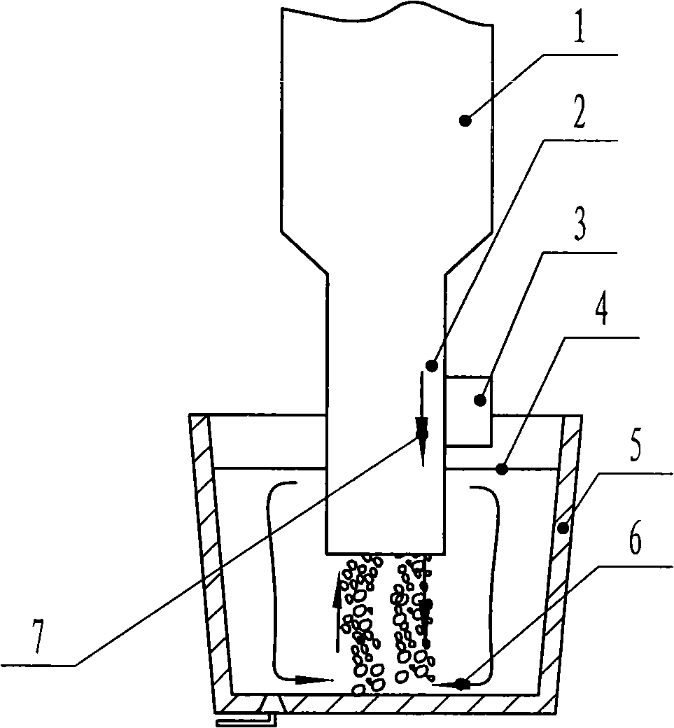
[0016] Embodiment one: figure 2 As shown, in this embodiment, a set of traveling wave magnetic field generators are installed on the right side of the suction nozzle periphery. When the magnetic field generator feeds the three-phase alternating current, a magnetic field is generated in the molten steel, and the magnetic field generates a current, and then generates a downward electromagnetic force, which together with the gas drives the molten steel to circulate rapidly downward, thus increasing the circulation of the molten steel flow.

Embodiment 2

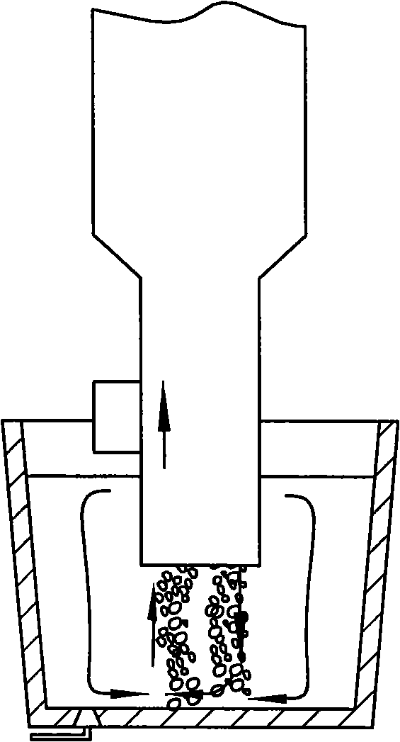
[0017] Embodiment two: image 3 As shown, in this embodiment, a set of traveling wave magnetic field generator is installed on the left side of the suction nozzle. When the magnetic field generator feeds three-phase alternating current, a magnetic field is generated in the molten steel, and the magnetic field generates a current, which in turn generates an upward electromagnetic force. , the electromagnetic force together with the gas drives the molten steel to circulate rapidly upwards, thereby increasing the circulating flow rate of the molten steel. All the other are the same as the first embodiment.

Embodiment 3

[0018] Embodiment three: Figure 4 As shown, in this embodiment, a set of traveling wave magnetic field generators are respectively installed on the left and right sides of the suction nozzle periphery. When the magnetic field generator is fed with three-phase alternating current, a magnetic field is generated in the molten steel, and the magnetic field generates a current, which in turn generates The electromagnetic force is upward on the left side and downward on the right side. Together with the gas, the electromagnetic force drives the molten steel to circulate rapidly upward and downward, thereby increasing the circulating flow of molten steel. All the other are the same as the first embodiment.


PUM


Abstract

The invention relates to a method and a device for improving the circulating flow of a single-jet refining furnace. A steel ladle holding molten steel is arranged under a suction nozzle of the single-jet refining furnace; the suction nozzle of the single-jet refining furnace extends to the molten steel; the molten steel flows through a vacuum chamber by the suction nozzle; the device is characterized in that the periphery of the suction nozzle of the single-jet refining furnace is provided with at least one set of traveling wave magnetic field generators; a mounting position of the traveling wave magnetic field generator exceeds the molten steel level; the traveling wave magnetic field generator can produce an electromagnetic force consistent with the circulating direction of the molten steel; and the electromagnetic force and gas together drive the molten steel to circularly flow, thereby increasing the circulating flow of the molten steel. The periphery of the suction nozzle of the single-jet refining furnace is provided with the magnetic field generator; when the molten steel is refined, the magnetic field generator is started so as to generate the electromagnetic force consistent with the flowing direction of the molten steel close to the suction nozzle, thereby increasing the circulating flow of the molten steel and achieving the aims of shortening the refining treatment time and improving the refining treatment efficiency.

Description

technical field [0001] The invention specifically relates to a method for increasing the circulating flow rate of a single nozzle refining furnace. Background technique [0002] RH refers to an integral or split vacuum chamber, and all metallurgical reactions during RH treatment are carried out in the vacuum chamber. There are two dipping pipes with refractory material as the inner and outer lining at the bottom, which are used after high-temperature baking, and the upper part is connected with the hot bend pipe, and then connected with the vacuum system. Various gases pass through the hot elbow, and the gas cooler is pumped out by the vacuum pump system and discharged to the atmosphere. [0003] When performing vacuum treatment, use a ladle car to send the ladle into the processing position, lower the vacuum chamber or lift the ladle, so that the suction nozzle can be immersed below the molten steel in the ladle. Then start the vacuum pump. Due to the pressure drop in th...

Claims


Application Information

Patent Timeline
IPC IPC(8): C21C7/00
Inventor 张春亮徐芳泓王立新崔天燮赵建伟周瑰云苗华军
Owner SHANXI TAIGANG STAINLESS STEEL CO LTD
Why Eureka
Try Eureka