Economical knitting controlling mechanism of computer flat-bed knitting machine

A technology of a flat knitting machine and a control mechanism, which is applied in the directions of weft knitting, knitting, textiles and paper making, can solve the problems of large size of triangular base plate, high production cost and large size of the machine head, and achieves reduced size and less consumables. , the effect of structure simplification

Inactive Publication Date: 2008-11-12
冯加林 +1
View PDF0 Cites 8 Cited by
  • Summary
  • Abstract
  • Description
  • Claims
  • Application Information

AI Technical Summary

Problems solved by technology

Therefore, the structure of the existing weaving control mechanism is relatively complicated, which makes the size of the triangular bottom plate larger
The knitting control mechanism is installed on the head of the computerized flat knitting machine, so the size of the head is correspondingly larger.
The machine head runs on the needle bed, so the size of the needle bed must increase accordingly, and the needle bed is a casting, so a larger bed body must consume more materials, resulting in high production costs

Method used


Image

  • Economical knitting controlling mechanism of computer flat-bed knitting machine
  • Economical knitting controlling mechanism of computer flat-bed knitting machine
  • Economical knitting controlling mechanism of computer flat-bed knitting machine

Examples


Embodiment Construction

[0020] The present invention and its advantages will be further described below in conjunction with the accompanying drawings and embodiments.

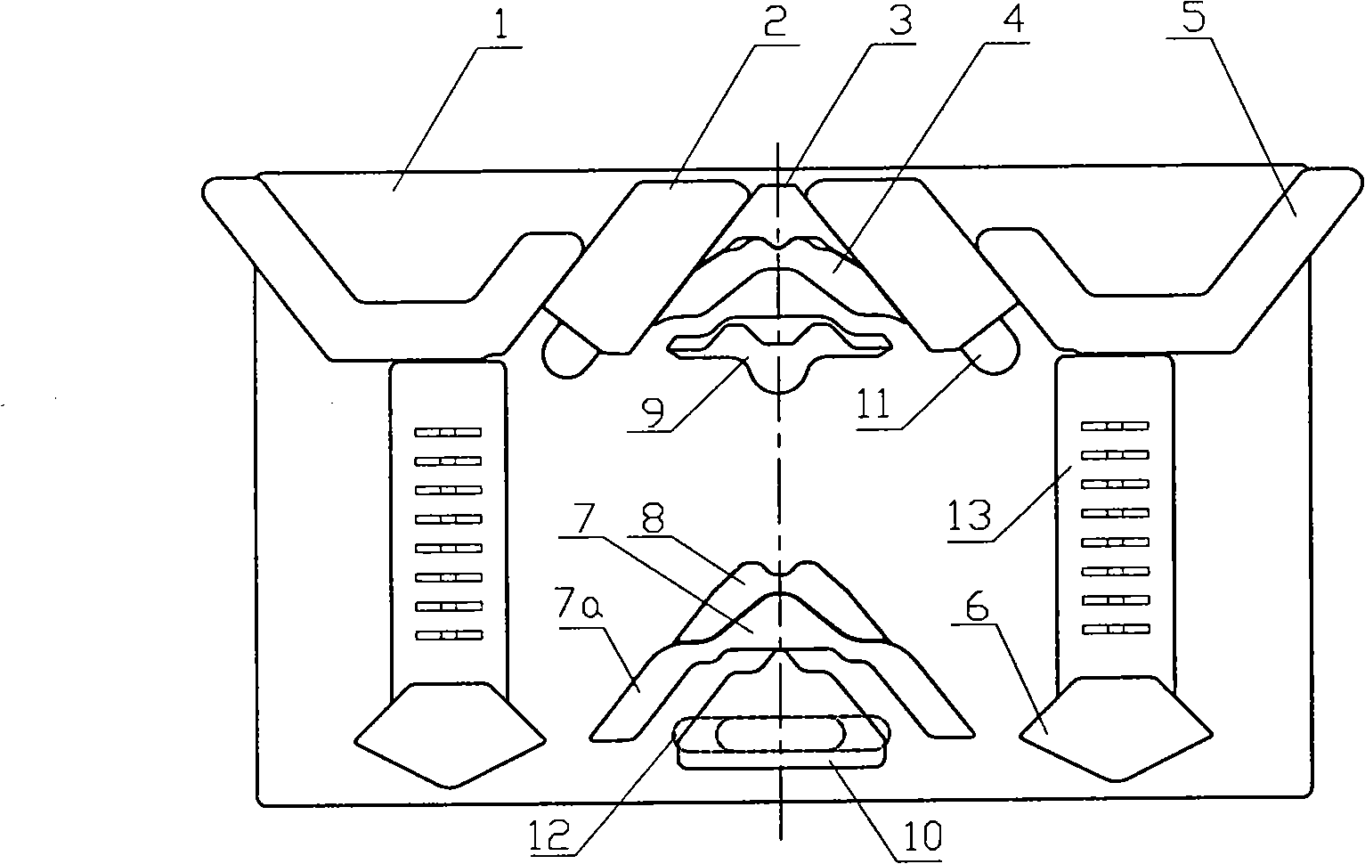
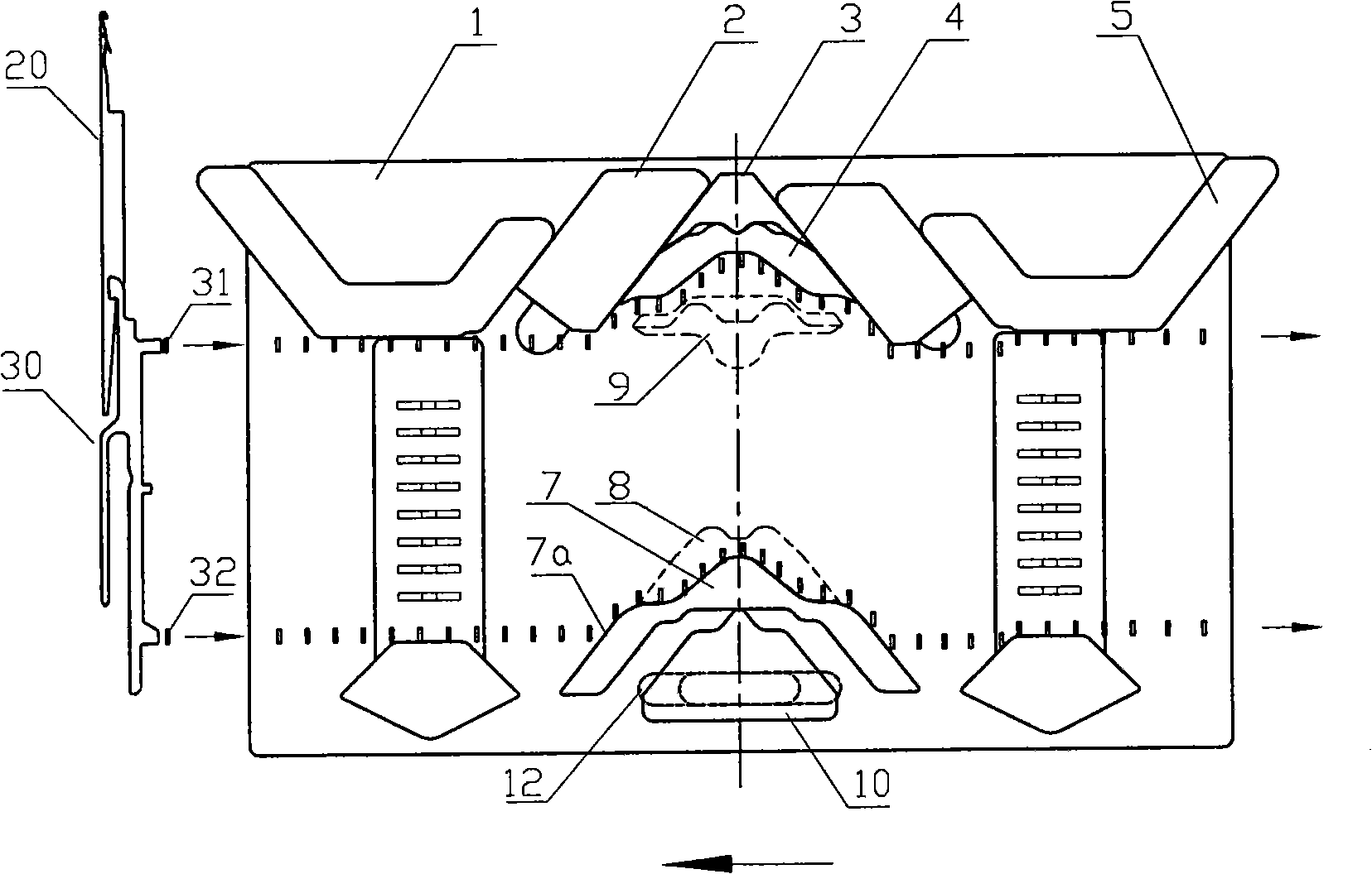
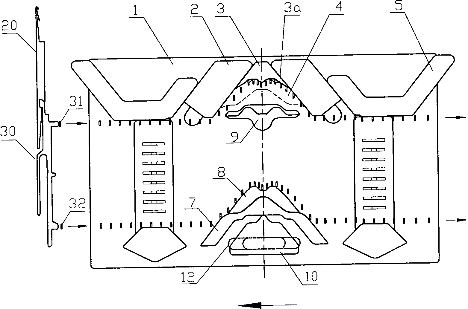
[0021] figure 1 It is a knitting control mechanism with a knitting unit. On the cam bottom plate 1, there are needle stop cam 5, loop transfer cam 3, needle press cam 2, loop receiving cam 9, loop transfer cam 8, and loop forming cam 7. Form a weaving area with the weaving triangles such as tuck triangles 10. In the upper part of this area, there are needle-blocking triangles 5 and needle-pressing triangles 2 symmetrically distributed. Needle selectors 13 are placed on both sides symmetrically in the middle of the area. A needle selection cam 6 and a needle raising cam 7a are symmetrically distributed in the lower part of the area, and the two stitching cams 7a and the knitting cam 7 are integrated. On the top of the center line of symmetry in this knitting area, there are transfer ring and stop needle triangle 3, eyebrow triangle...


PUM


Abstract

The invention relates to a knitting control mechanism of an economical computerized flat knitting machine, which is positioned on a triangular bottom board and provided with at least one knitting unit. Each knitting unit consists of knitting cams controlling the knitting action of a knitting needle and a needle selector and a needle selection cam controlling the knitting needle in the knitting condition, wherein, the knitting cams consist of a transfer needle retracting cam, a depressing cam, an adapter needle retracting cam, a transfer cam, a stitch cam and a tuck cam. The distribution of the knitting cams on the triangular bottom board forms a knitting area, wherein, the needle selector and needle selection cam are arranged in the knitting area, the needle selector is positioned in the middle of the area, the needle selection cam is at the bottom of the area; the knitting cams are: the transfer needle retracting cam, an eyebrow cam, the adapter needle retracting cam, and the depressing cam are arranged on the upper part of the knitting area, and the transfer cam, the stitch cam and the tuck cam are arranged at the lower part of the knitting area. The invention has the advantages of simplified and compact structure, small-volume whole machine, low material consumption, low price and good knitting property.

Description

technical field [0001] The invention relates to a flat knitting machine, in particular to a knitting control mechanism of an economical computerized flat knitting machine. Background technique [0002] The knitting control mechanism of the computerized flat knitting machine is set on the triangular bottom plate and generally consists of multiple knitting units. Each knitting unit is composed of a knitting area I distributed on the upper side of the triangular base plate, a platen area II distributed in the middle of the triangular base plate, and a needle selection area III distributed on the lower side of the triangular base plate, as shown in FIG. 8 . Various knitting cams are arranged in the knitting area, wherein the main knitting cams are: transfer cam 102 , press cam 103 , eyebrow cam 104 , loop forming cam 105 , transfer cam 106 and tuck cam 107 . The stitch transfer cam 102 and the stitch transfer cam 106 are located in the upper half of the knitting area, and the e...

Claims


Application Information

Patent Timeline
Patent Type & Authority Applications(China)
IPC IPC(8): D04B15/36
Inventor 冯加林巫友群
Owner 冯加林
Why Eureka
Try Eureka