Arrangement combination of U type pipe in solar water heater heat collection gate as well as overlapped structure thereof

A technology of arrangement and combination of solar water heaters, applied in the direction of solar collectors, solar thermal energy, solar collectors using working fluid, etc., to achieve smooth convection, increase the heating area, and improve the heat gain effect

Active Publication Date: 2010-06-23
刘博雅
View PDF1 Cites 0 Cited by
  • Summary
  • Abstract
  • Description
  • Claims
  • Application Information

AI Technical Summary

Problems solved by technology

It solves the disadvantages of installing an integrated solar water heater on the roof. The reason why it is necessary to install solar cells on the collector to power the water pump configured at the outlet pipe to promote water circulation is because the installation space of the balcony is limited. , the heat collector generally needs to be placed horizontally outside the balcony, and the water in the heat collector and the water storage tank cannot form convection, resulting in the low temperature of the water in the water storage tank, which cannot meet the needs of domestic hot water
Although the solar water heater disclosed by the application number 200610147392.X solves the problem of slow heat exchange between the heat collector and the water storage tank, it greatly increases the cost and after-sales service of the solar water heater due to the need to install solar cells and water pumps on the heat collector quantity, not suitable for promotion and use

Method used


Image

  • Arrangement combination of U type pipe in solar water heater heat collection gate as well as overlapped structure thereof
  • Arrangement combination of U type pipe in solar water heater heat collection gate as well as overlapped structure thereof
  • Arrangement combination of U type pipe in solar water heater heat collection gate as well as overlapped structure thereof

Examples


Embodiment 1

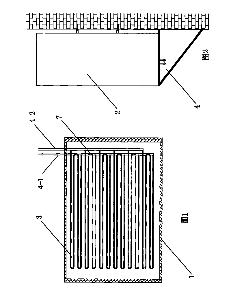
[0022] Embodiment 1: As shown in Figures 1 and 2, the solar water heater of the present invention is a split structure. The heat collecting grid 1 is placed horizontally on the outer wall of the balcony fence, and the water storage tube 2 is installed on the wall in the balcony. The tube 4 communicates with the U-shaped tube 3 in the heat collecting grid, and two exchange tubes are arranged side by side, including a cold exchange tube 4-1 and a heat exchange tube 4-2.

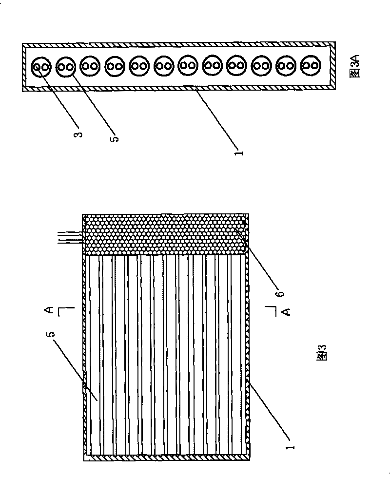
[0023] As shown in Figures 1, 3, and 3A, 12 vacuum tubes 5 with one end open are arranged up and down and installed horizontally in the heat collector grid 1, and 12 U-shaped tubes are correspondingly placed horizontally in the 12 vacuum tubes, and each 2 U-shaped tubes are placed between the vacuum tubes. The open ends are connected in series through the elbow 7 to form a heat collecting tube group with one water inlet pipe and one water outlet pipe. 6 water inlet pipes of 6 heat collecting pipe groups are con...

Embodiment 2

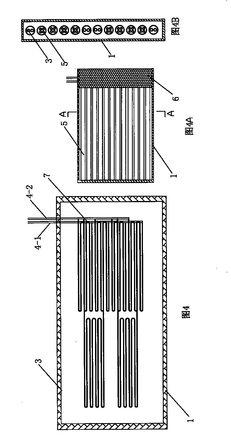
[0027] Embodiment 2: As shown in Figures 4, 4A, and 4B, 12 vacuum tubes 5 with one end open are arranged up and down and installed horizontally in the heat collecting grid 1, and 12 U-shaped tubes are correspondingly placed horizontally in 12 vacuum tubes, and each 3 U-shaped tubes The tubes are connected in series through the elbow 7 at the open end of the vacuum tube to form a heat collecting tube group with a water inlet pipe and a water outlet pipe. The water inlet pipe is located below the heat collecting tube group, and the water outlet pipe is located above the heat collecting tube group. 4 heat collecting tube groups, 4 water inlet pipes of the 4 heat collecting tube groups are connected in parallel on the cold exchange pipe 4-1, and 4 water outlet pipes are connected in parallel on the heat exchange pipe 4-2. Then divide the 8 U-shaped tubes into 2 heat-collecting tube groups, and each 4 U-shaped tubes are connected in series through an elbow to form a heat-collecting ...

Embodiment 3

[0028]Embodiment 3: As shown in Figures 5, 5A, and 5B, 12 vacuum tubes 5 with one end open are arranged up and down and installed horizontally in the heat collecting grid 1, and 12 U-shaped tubes are correspondingly placed horizontally in 12 vacuum tubes, and each 4 U-shaped tubes The tubes are connected in series through the elbow 7 at the open end of the vacuum tube to form a heat collecting tube group with a water inlet pipe and a water outlet pipe. The water inlet pipe is located below the heat collecting tube group, and the water outlet pipe is located above the heat collecting tube group. 3 heat collecting tube groups, 3 water inlet pipes of the 3 heat collecting tube groups are connected in parallel on the cold exchange pipe 4-1, and 3 water outlet pipes are connected in parallel on the heat exchange pipe 4-2. Then divide the 6 U-shaped tubes into 3 heat-collecting tube groups, each 2 U-shaped tubes are connected in series through an elbow to form a heat-collecting tube ...


PUM


Abstract

The invention discloses a proposal for the permutation, the combination and the superposition design of U-shaped pipes in the heat collection grid of a solar water heater. The U-shaped pipes in a vacuum pipe are connected in series and then in parallel on two exchanging pipes; the U-shaped pipes form heat collection pipe groups by connection in series, thus prolonging the retention time of water in the U-shaped pipes and raising the heat obtaining rate of the water; besides, the water inlet pipes and the water outlet pipes of a plurality of the heat collection pipe groups are respectively connected in parallel on cold exchanging pipes and heat exchanging pipes, and the sum of the cross section of the water outlet pipes is set to be very close to the section of the heat exchanging pipes, thereby greatly improving the convective velocity of cold and hot water.

Description

Technical field: [0001] The invention relates to a solar water heater, in particular to an improvement on the arrangement and combination of U-shaped tubes in the heat collecting grid of the solar water heater and the superposition structure. Background technique: [0002] As we all know, most of the existing solar water heaters are installed obliquely on the roof, and for high-rise buildings, because the area of ​​the roof is limited, it is unrealistic for every household to install the water heater on the roof, and this The heat collecting tube and the water tank of the water heater are of an integrated structure, which is heavy and inconvenient to install on the roof, and maintenance and maintenance are all relatively troublesome; moreover, the upper and lower water pipes of this water heater are very long, which will cause a large amount of heat loss. Therefore, the Chinese patent "split-type solar water heater" with application number 200610147392.X discloses a split-t...

Claims


Application Information

Patent Timeline
Patent Type & Authority Patents(China)
IPC IPC(8): F24J2/05F24J2/46F24S10/40
CPCY02E10/44
Inventor 刘建光
Owner 刘博雅
Why Eureka
Try Eureka