Colored filter with spacer, liquid crystal display device and method for making the same

A technology of color filter and manufacturing method, which is applied in the photoplate-making process, instruments, optics and other directions of the pattern surface, can solve the problems such as the uncontrollable distribution of LCD spacers, achieve brightness, avoid the influence of pixels, and improve Effects of Brightness and Uniformity

Inactive Publication Date: 2008-11-12
BYD CO LTD
View PDF0 Cites 44 Cited by
  • Summary
  • Abstract
  • Description
  • Claims
  • Application Information

AI Technical Summary

Problems solved by technology

[0004] The main purpose of the present invention is to solve the technical problem that the distribution of LCD spacers cannot be controlled in the prior art, and to provide a method for manufacturing a color filter that can directly form spacers on the substrate, so that the distribution position area of ​​​​the spacers can be controlled

Method used


Image

  • Colored filter with spacer, liquid crystal display device and method for making the same
  • Colored filter with spacer, liquid crystal display device and method for making the same
  • Colored filter with spacer, liquid crystal display device and method for making the same

Examples


Embodiment approach 1

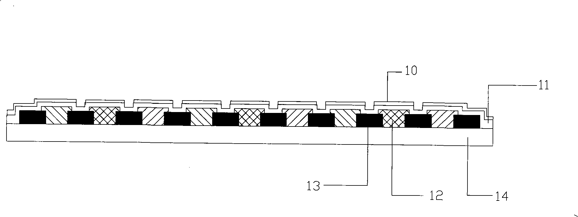
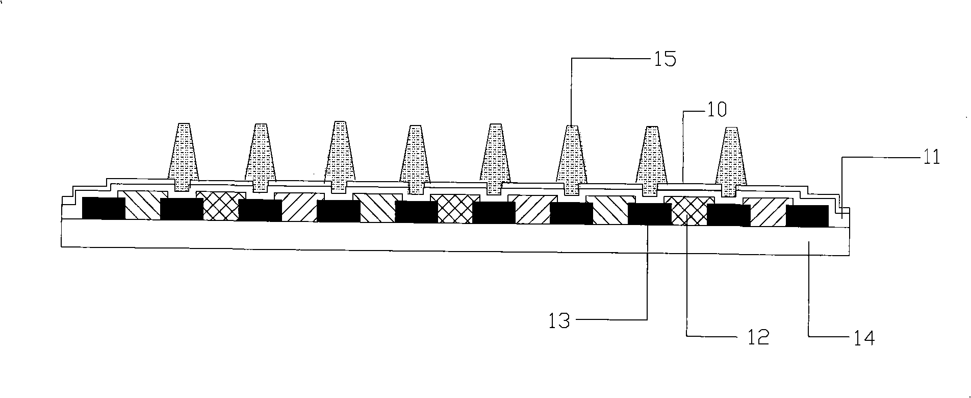
[0037] Embodiment 1. In this embodiment, spacers are formed on the top of the color filter substrate. The color filter substrate can use various existing color filters. The existing color filters are usually composed of A transparent SiO coated 2 On the glass substrate of the thin film, a black matrix for shading and a red film layer, a green film layer, a blue film layer arranged in a certain order and a transparent film layer for flattening and protecting the surface are arranged on the transparent substrate. Composition of flat layers. A typical existing color filter structure such as figure 1 shown, including a SiO-coated 2 The film is composed of a glass substrate 14, a black matrix layer 13, a color filter layer 12 including a plurality of color pixels, a flat layer 11, and an electrode layer 10 engraved with a pattern. The black matrix layer 13 is disposed on the surface of the glass substrate 14, and the black matrix layer is composed of horizontally and vertically ...

Embodiment approach 2

[0050] Embodiment 2 is different from Embodiment 1 in that the spacers are formed on the surface of the first substrate facing the color filter substrate. The first substrate can adopt various existing TFT substrates or white glass substrates, and the existing first substrates usually include a transparent SiO coated 2 The glass substrate of the thin film and the transparent electrode layer formed on the glass substrate adopt the manufacturing method in Embodiment 1, and the spacers are formed on the glass substrate and the transparent electrode layer through exposure and lithography. The position of the spacer is set so that the first substrate and the color filter are assembled to correspond to the area of ​​the black matrix of the color filter, preferably the position of the spacer and the grid lines of the black matrix of the color filter Corresponds to the location area of ​​the intersection point. After the first substrate and the color filter are assembled, the top of ...


PUM


Abstract

The invention discloses a colorful optical filter base plate with fixed spacers and a manufacturing method thereof. The colorful optical filter comprises a transparent substrate, a colorful film layer, a latticed black matrix, a flat layer, a transparent electrode layer and a columnar spacer. Firstly, the well-known colorful optical filter base plate is coated with transparent photosensitive material and then exposed by a mask with preset patterns, after being treated by adopting micro-lithography, the transparent columnar or frustum-shaped spacers are directly formed on the colorful optical filter base plate; the central shafts of the spacers are perpendicular to the surface of the flat layer and corresponding to the intersection of gridlines of the black matrix. Since the spacers are directly formed on the colorful optical filter base plate and the height, distribution and density thereof are all preset and controllable, the liquid crystal thickness (CELL GAP) between LCD base plates can be kept uniform, thus avoiding arranging the spacers within a pixel to affect the porosity of LCD.

Description

【Technical field】 [0001] The invention relates to a color filter, a liquid crystal display and a manufacturing method thereof. 【Background technique】 [0002] In an LCD (Liquid Crystal Display), a liquid crystal layer is usually disposed between two substrates. For a TFT liquid crystal display, where a first transparent electrode layer and a TFT (thin film transistor) switch are formed on the first substrate, the first substrate is generally called a TFT substrate. For a CSTN liquid crystal display, the first transparent electrode layer is formed on the first substrate, which is called a white glass substrate. A color filter layer including a plurality of color pixels and a second transparent electrode layer are formed on the second substrate, which is generally called a color filter substrate. Color filter is the key component to realize the colorization of LCD. When combining the first substrate and the second substrate, in order to control the thickness of the liquid c...

Claims


Application Information

Patent Timeline
Patent Type & Authority Applications(China)
IPC IPC(8): G03F7/00G02B5/23G02F1/1333
Inventor 朱保平
Owner BYD CO LTD
Why Eureka
Try Eureka