Soil discharging control method of center drive mono-tube soil sucker

A technology of central transmission and control method, applied in separation methods, chemical instruments and methods, feed/discharge devices of sedimentation tanks, etc. and other problems to achieve the effect of reducing backflow, reducing energy consumption and improving safety

Inactive Publication Date: 2008-11-19
GUANGZHOU NEWEARTH ENVIRONMENTAL PROTECTION IND
View PDF0 Cites 6 Cited by
  • Summary
  • Abstract
  • Description
  • Claims
  • Application Information

AI Technical Summary

Problems solved by technology

[0006] The use of reflux ratio is an extensive control method, because the water volume of the sewage treatment plant is constantly changing during the operation process, and because the growth of sludge, that is, microorganisms, requires a certain time and process, it leads to changes in water volume and sludge The change of concentration is not corresponding in real time, but there is a certain lag in time. Therefore, simply relying on the change of water volume to adjust the amount of return sludge will lead to a low concentration of return sludge and a large range of changes, which will affect the biochemical pool. The stable operation of the system has a certain impact, and increases the energy consumption of the reflux system

Method used


Image

  • Soil discharging control method of center drive mono-tube soil sucker
  • Soil discharging control method of center drive mono-tube soil sucker
  • Soil discharging control method of center drive mono-tube soil sucker

Examples


Embodiment 1

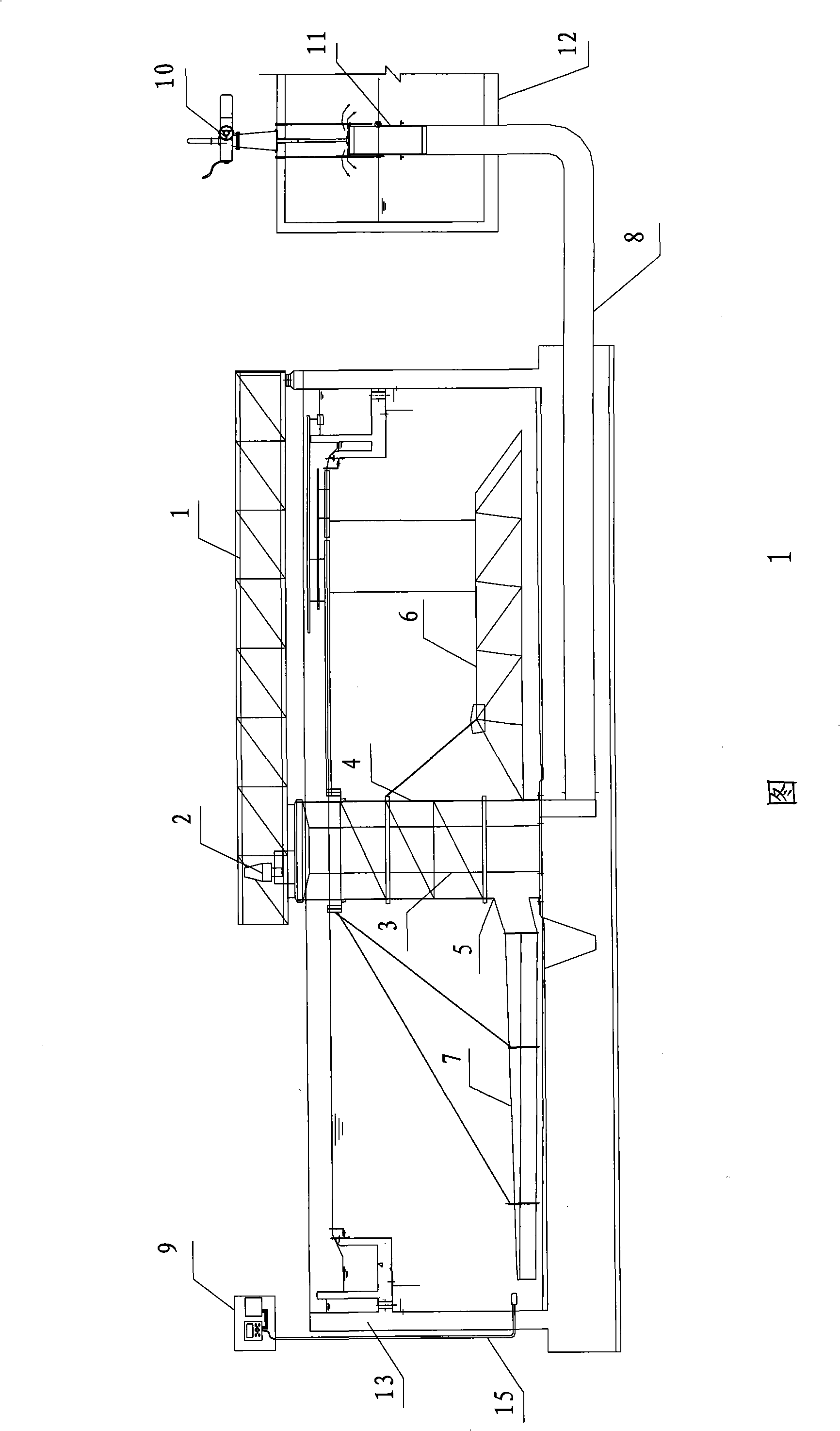
[0025] Referring to Fig. 1, it is a schematic structural view of a centrally driven single-pipe dredger of the present invention, the centrally driven single-pipe dredger is composed of a drive mechanism 2, a rotating cage 4, a mud collection tube 5, and a truss arranged at the sedimentation tank 13. 6. The mud suction pipe 7, the mud discharge pipe 8, the mud discharge valve 11, the electric actuator 10, the sludge concentration meter 15 and the controller 9 are composed, wherein the drive mechanism 2 is arranged on the top of the central column 3 in the middle of the sedimentation tank 13, and turns The cage 4 is set on the outer periphery of the center column 3, and the mud collection tube 5 is set outside the center column 3 at the bottom of the tumbler 4, and is connected to the suction pipe 7, and the inside is connected to the mud discharge pipe 8 through a fan-shaped well, and the mud discharge pipe 8 is connected to the The port of the mud discharge well 12 and the sed...

Embodiment 2

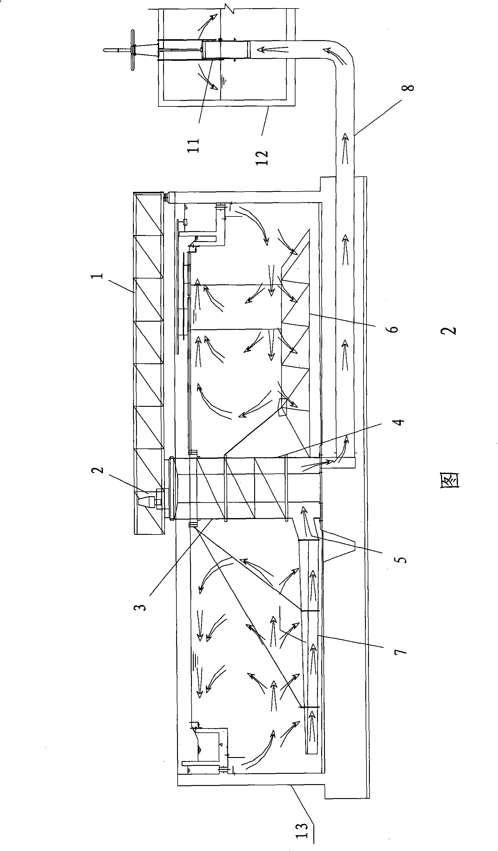
[0039] Referring to Fig. 4, it is a schematic structural view of another central drive single-pipe dredger of the present invention, and its structural difference from Embodiment 1 is that in this embodiment, the sludge concentration meter 15 is arranged in the mud discharge well 12 , collect the sludge concentration in the sludge discharge well 12 in real time, and transmit the sludge concentration signal to the controller 9, and the controller 9 controls the electric actuator 10 to adjust the opening degree of the sludge discharge valve 11 according to the state of the sludge concentration. The mud concentration signal is directly proportional to the relationship. The sludge concentration meter 15 can also be arranged in the sludge discharge pipe 8 which is also the sludge discharge channel, and the corresponding sludge discharge valve 11 can also be arranged on the sludge discharge pipe 8 .

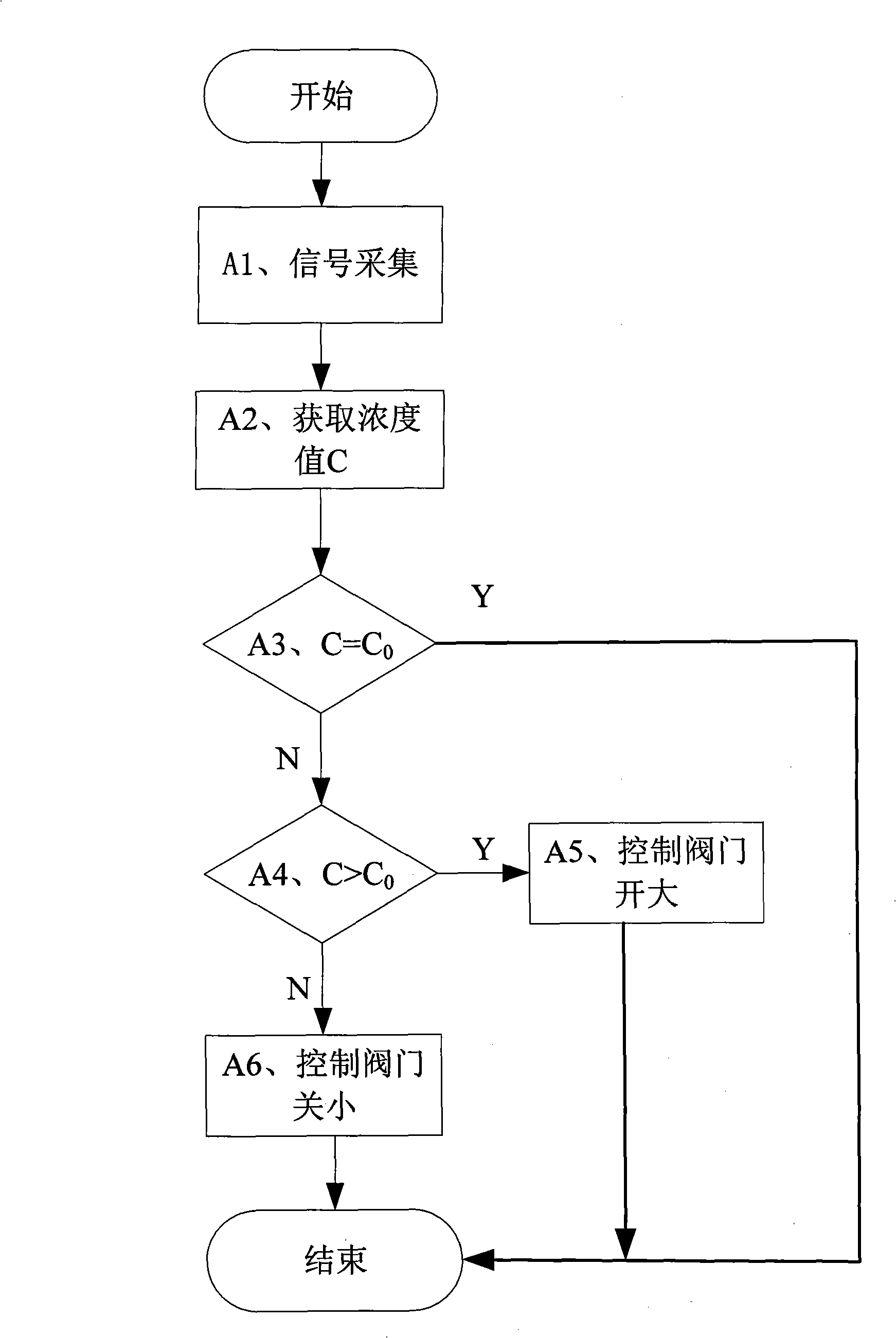
[0040] refer to Figure 5 , to further illustrate the mud discharge control proce...

Embodiment 3

[0048] Referring to Fig. 6, it is a structural schematic diagram of another central drive single-pipe dredger of the present invention, and its structural difference from Embodiment 1 is that: the sludge interface instrument 14 is used to collect the sludge state signal of the sedimentation tank, and set In the sedimentation tank 13, the sludge layer height H at the bottom of the sedimentation tank 13 is collected in real time, and the sludge layer height H signal is transmitted to the controller 9, and the controller 9 judges the sludge state at this time according to the sludge layer height H signal , control the electric actuator 10 to adjust the opening of the sludge valve 11 and the sludge layer height H signal is proportional to the relationship. Due to the large surface area of ​​the sedimentation tank and the disturbance of the bottom water flow, it may be difficult for the height of the sludge layer at a certain point or in a small area to represent the status of the s...


PUM


Abstract

The invention discloses a control method for the sludge discharge of a center-drive single-pipe suction dredge, and the control method controls the opening degree of a sludge discharge valve to be directly proportional to a sludge state signal according to the sludge state by detecting the sludge state and outputting the corresponding sludge state signal. The control method has the advantages that the control method changes the traditional control mode of artificially regulating the sludge discharge valve to regulate the sludge discharge amount, thereby allowing the operation of a system to be more in line with the dynamic changing law; the control is more accurate and direct by obtaining the on-line sludge state signal and regulating the opening degree of the sludge discharge valve, the sludge concentration can be stabilized within a higher scope of 10 to 12g/L by the control method, thereby lowering the return sludge volume of a biochemical system and reducing the energy consumption of a sludge return system by 30 to 50 percent, and the energy consumption of a whole municipal sewage treatment plant can even be reduced by about 2 to 4 percent.

Description

technical field [0001] The invention belongs to the field of sewage treatment, and in particular relates to a control method for sludge discharge of a mechanical sludge discharge device of a sedimentation tank of an urban domestic sewage treatment plant and an industrial wastewater treatment plant. Background technique [0002] The sedimentation tank sludge removal machinery of urban domestic sewage treatment plants has been developed for more than half a century from the 1950s to the present. Its development can be roughly divided into three stages: manual sludge discharge, mechanical sludge scraping and mechanical sludge suction. [0003] Manual sludge removal is cumbersome and prone to problems such as poor mud discharge and mud accumulation in the pool, which affects the water outlet effect; mechanical mud scraping is prone to sedimentation upturning, high moisture content in the discharged mud, and affected water quality; mechanical mud suction Compared with the previou...

Claims


Application Information

Patent Timeline
Patent Type & Authority Applications(China)
IPC IPC(8): B01D21/30B01D21/24
Inventor 郑辉周相武郑利平钟佳梅
Owner GUANGZHOU NEWEARTH ENVIRONMENTAL PROTECTION IND
Why Eureka
Try Eureka