

Sintered flue gas dry-method removal method and device
A sintering flue gas removal technology, which is applied in separation methods, chemical instruments and methods, and separation of dispersed particles, can solve problems such as difficult removal of harmful gas and inability to adapt to large-scale changes in flue gas volume.
- Summary
- Abstract
- Description
- Claims
- Application Information
AI Technical Summary
Problems solved by technology
Method used
Image

Examples
Embodiment Construction
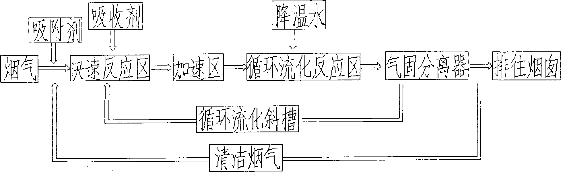
[0019] figure 1 The shown sintering flue gas dry removal method comprises the following steps:
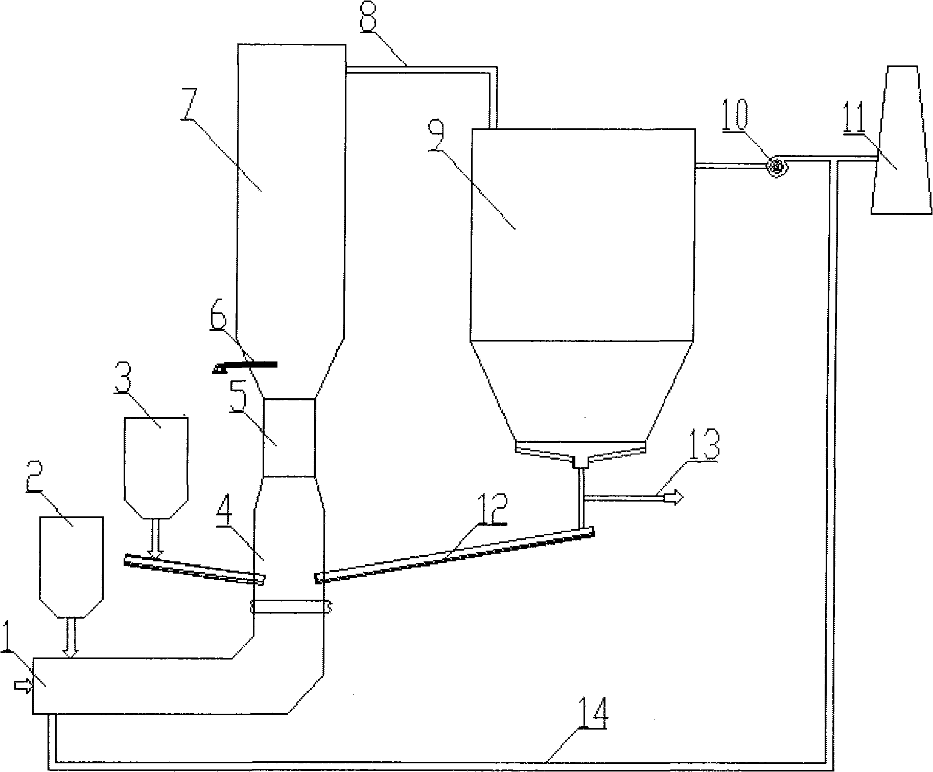
[0020] 1) When the high-temperature flue gas enters the rapid mixing zone 4, the absorbent is added, and the absorbent is pre-mixed and pretreated with the flue gas in the rapid mixing zone 4 to remove part of SO 2 , SO 3 , heavy metals, dioxins, most HCL, HF gases;
[0021] 2) The flue gas coming out of the rapid mixing zone 4 enters the circulating fluidized reaction zone 7 after being accelerated by the accelerating zone 5, and sprays water at the front end of the circulating fluidized reaction zone 7 to cool down, and continues to remove the residual gas in the circulating fluidized reaction zone 7. SO 2 , SO 3 , heavy metals, dioxin components;
[0022] 3) The purified flue gas enters the gas-solid separator 9 through the outlet flue 8 of the reaction tower, the desulfurization ash is captured by the gas-solid separator 9, and enters the rapid mixing zone 4 through the ci...
PUM
 Abstract
Description
Claims
Application Information