Production method of hollow turbine vane with shaped air film hole

A technology for turbine blades and manufacturing methods, which is applied in the field of manufacturing hollow turbine blades, and can solve problems affecting blade fatigue life, blade fatigue fracture, etc.

Inactive Publication Date: 2008-11-19
XI AN JIAOTONG UNIV
View PDF0 Cites 36 Cited by
  • Summary
  • Abstract
  • Description
  • Claims
  • Application Information

AI Technical Summary

Problems solved by technology

The existence of these defects directly affects the fatigue life of the blade, and more seriously, it will lead to fatigue fracture of the blade during work, resulting in very serious consequences. Therefore, the design d

Method used


Image

  • Production method of hollow turbine vane with shaped air film hole

Examples


Embodiment 1

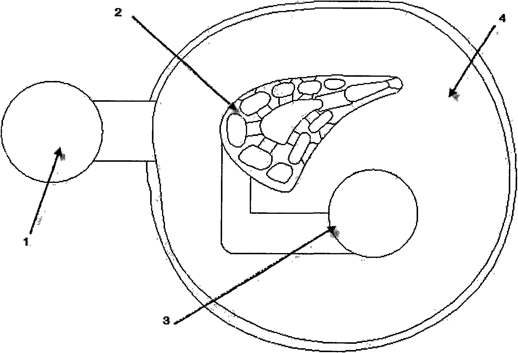
[0019] Example 1, see figure 1 , 1) Manufacture resin mold

[0020] The resin mold in this embodiment mainly consists of four parts, including ceramic slurry injection system prototype 1, hollow turbine blade prototype 2 with special-shaped air film holes, metal pouring system prototype 3 and mold cavity 4. The hollow turbine blade prototype 2 with special-shaped air film holes has a complex cooling structure inside, and there are many special-shaped air film holes on the outer surface. Through the ceramic slurry pouring system prototype 1, the ceramic slurry is smoothly filled into the mold cavity 4 and the internal cooling channel of the hollow turbine blade prototype 2 and the special-shaped air film holes on the outer surface. The mold cavity 4 is the mold shell of the ceramic casting mold, and its size is controlled between 6-8 mm, so as to avoid being too thick and affecting the metallurgical process performance of the ceramic casting mold and affecting the quality of t...

Embodiment 2

[0037] Example 2: Prepare ceramic slurry in this example: first dissolve organic matter in deionized water, add dispersant and uniformly mixed ceramic powder and mineralizer powder in turn to make ceramic slurry, add initiator and catalyst before pouring , mixed evenly and vacuumed to remove the air bubbles in the ceramic slurry to make a ceramic slurry with a viscosity of less than 1Pa S and a linear shrinkage rate of less than 0.5%; pour the ceramic slurry into the cavity of the hollow turbine blade prototype resin mold through the pouring system In the process, the hollow turbine blade prototype resin mold surface is filled with special-shaped air film holes and internal cooling channels, and the internal and external structures of the hollow turbine blade prototype are copied;

[0038] Among them, the ceramic powder adopts fused corundum powder with a particle size of 1-60 μm;

[0039] The mineralizer powder adopts magnesium oxide and yttrium oxide mixed in a mass ratio of...

Embodiment 3

[0045] Example 3: Preparation of ceramic slurry in this example: First, dissolve organic matter in deionized water, add dispersant and uniformly mixed ceramic powder and mineralizer powder in turn to make ceramic slurry, add initiator and catalyst before pouring , mixed evenly and vacuumed to remove the air bubbles in the ceramic slurry to make a ceramic slurry with a viscosity of less than 1Pa S and a linear shrinkage rate of less than 0.5%; pour the ceramic slurry into the cavity of the hollow turbine blade prototype resin mold through the pouring system In the process, the hollow turbine blade prototype resin mold surface is filled with special-shaped air film holes and internal cooling channels, and the internal and external structures of the hollow turbine blade prototype are copied;

[0046] Among them, the ceramic powder adopts fused corundum powder with a particle size of 1-60 μm;

[0047] The mineralizer powder adopts magnesium oxide and yttrium oxide mixed in a mass ...


PUM

PropertyMeasurementUnit
Particle sizeaaaaaaaaaa
Viscosityaaaaaaaaaa

Abstract

A method for producing hollow turbine blades with special-shaped film holes is provided. The method comprises the following steps: adopting the stereo-lithography technology to produce a resin die comprising a hollow turbine blade prototype with the special-shaped film holes; pouring ceramic slurry into a die cavity of the resin die; padding the special-shaped film holes and the inner cooling channel of the hollow turbine blade surface; copying the inner and the outer structures of the hollow turbine blade prototype; in-situ forming the ceramic slurry under the action of a catalytic agent and an evocating agent to form a ceramic body; drying for ignition lost of the resin die and sintering; obtaining a ceramic mould comprising inner and outer mould cores; finally pouring the high-temperature metal liquid into the ceramic mould; removing the ceramic mould after freezing forming and cooling the metal; and obtaining the hollow turbine blades with the special-shaped film holes. The method is mainly suitable for producing the hollow turbine blade precision casting with the special-shaped film holes, solves the problem of difficulty in processing forming the special-shaped film holes, and provides the method for producing the precision casting with special-shaped holes formed on the surface thereof.

Description

technical field [0001] The invention relates to the technical field of precision casting, in particular to a method for manufacturing a hollow turbine blade with a special-shaped air film hole. Background technique [0002] As one of the key technologies for cooling the hollow turbine blades of high-performance aero-engines, film cooling has been developed for decades, and with the continuous increase of gas temperature, film cooling technology is also continuously developed and improved, from the original The application of low blowing ratio develops to the application of high blowing ratio, and the air film hole shape also evolves from the initial cylindrical hole to the non-cylindrical hole. It first developed into a hole shape with outlet expansion, which is represented by fan-shaped holes, and then proposed a contraction-expansion hole to make the air film better adhere to the wall surface, and the air film cooling efficiency is higher. [0003] Existing laser processi...

Claims


Application Information

Patent Timeline
IPC IPC(8): B22D25/02B22C9/00
Inventor 李涤尘吴海华郭楠楠崔峰录孙博徐东阳
Owner XI AN JIAOTONG UNIV
Why Eureka
Try Eureka