Eureka AIR delivers breakthrough ideas for toughest innovation challenges, trusted by R&D personnel around the world.

Improved evaporation refrigeration air conditioner

An evaporative refrigeration and air conditioner technology, applied in the field of air conditioning equipment, can solve the problems of reducing the evaporative heat absorption area of ​​the heat exchanger, the heat exchange area of ​​the heat exchanger, and the heat exchange efficiency, etc., so as to increase the evaporative cooling area, The effect of sufficient heat exchange contact and noise reduction

Inactive Publication Date: 2011-07-20
申泽刚 +2
View PDF2 Cites 0 Cited by
  • Summary
  • Abstract
  • Description
  • Claims
  • Application Information

AI Technical Summary

Problems solved by technology

However, when the induced draft fan flows a large amount of air through the direct heat exchanger at a certain speed, the water flowing from top to bottom along the heat exchanger plate is blown by the flowing air, causing the water flow to deviate from the direction of the air flow. There is no water film on the area of ​​a part of the plate surface in the heat exchanger, which reduces the evaporation and heat absorption area of ​​the heat exchanger
In addition, since the heat exchanger is made of corrugated plates, when water flows on the corrugated plates, there will be no water film covering the convex or concave parts of the corrugated plates.
In this way, the heat exchange area of ​​the heat exchanger is reduced, and the heat exchange efficiency is reduced.

Method used


Image

  • Improved evaporation refrigeration air conditioner
  • Improved evaporation refrigeration air conditioner
  • Improved evaporation refrigeration air conditioner

Examples


Embodiment Construction

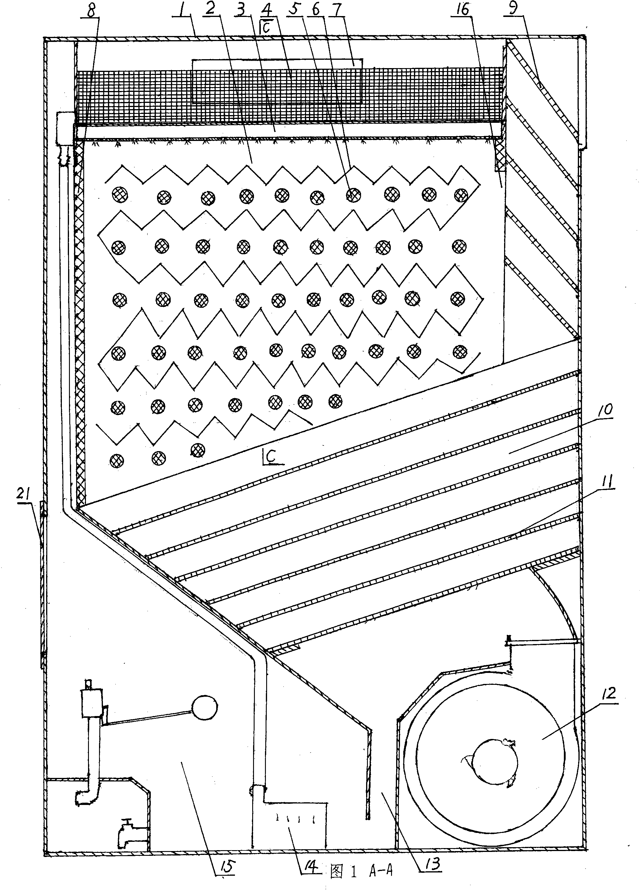
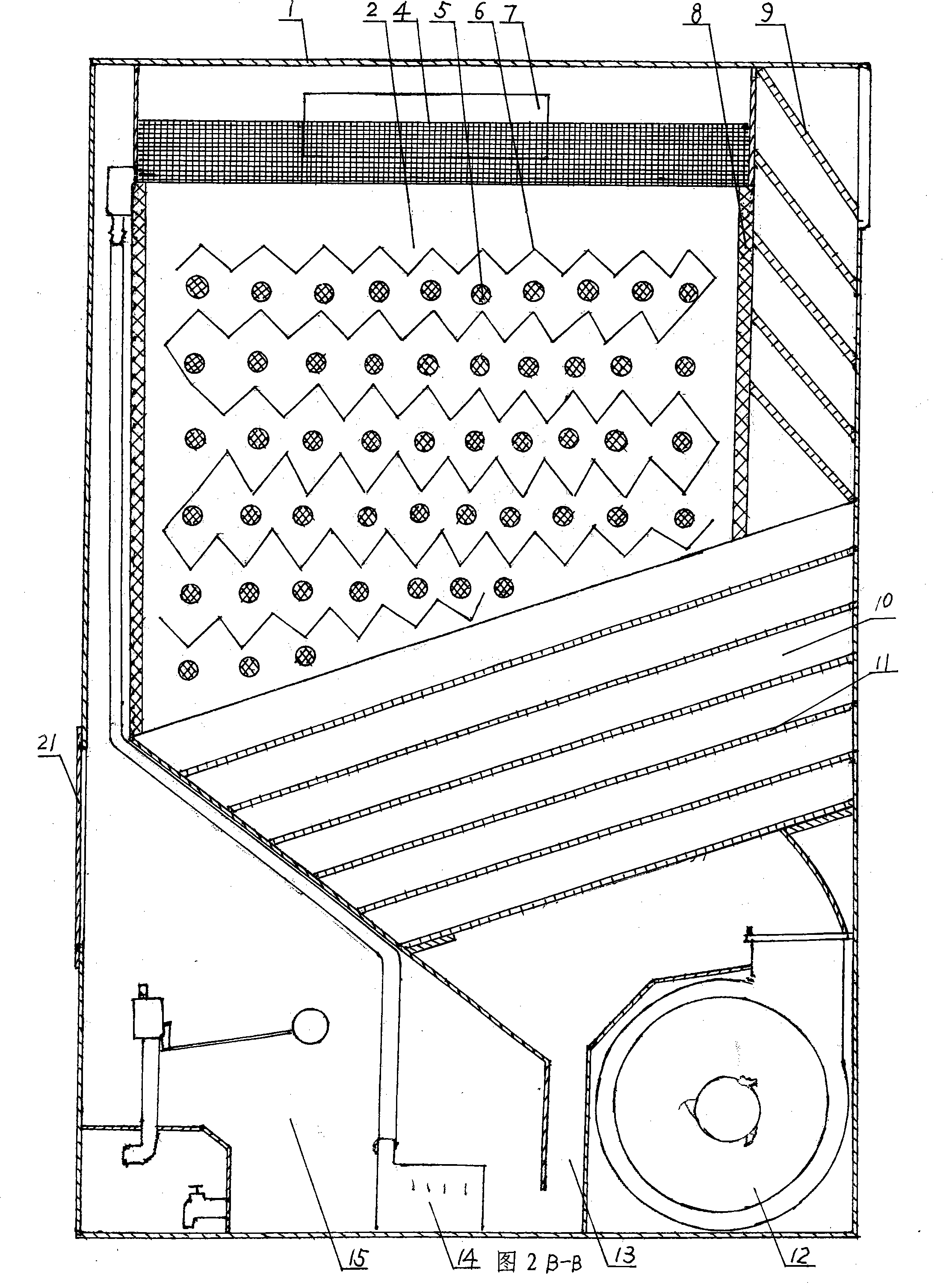
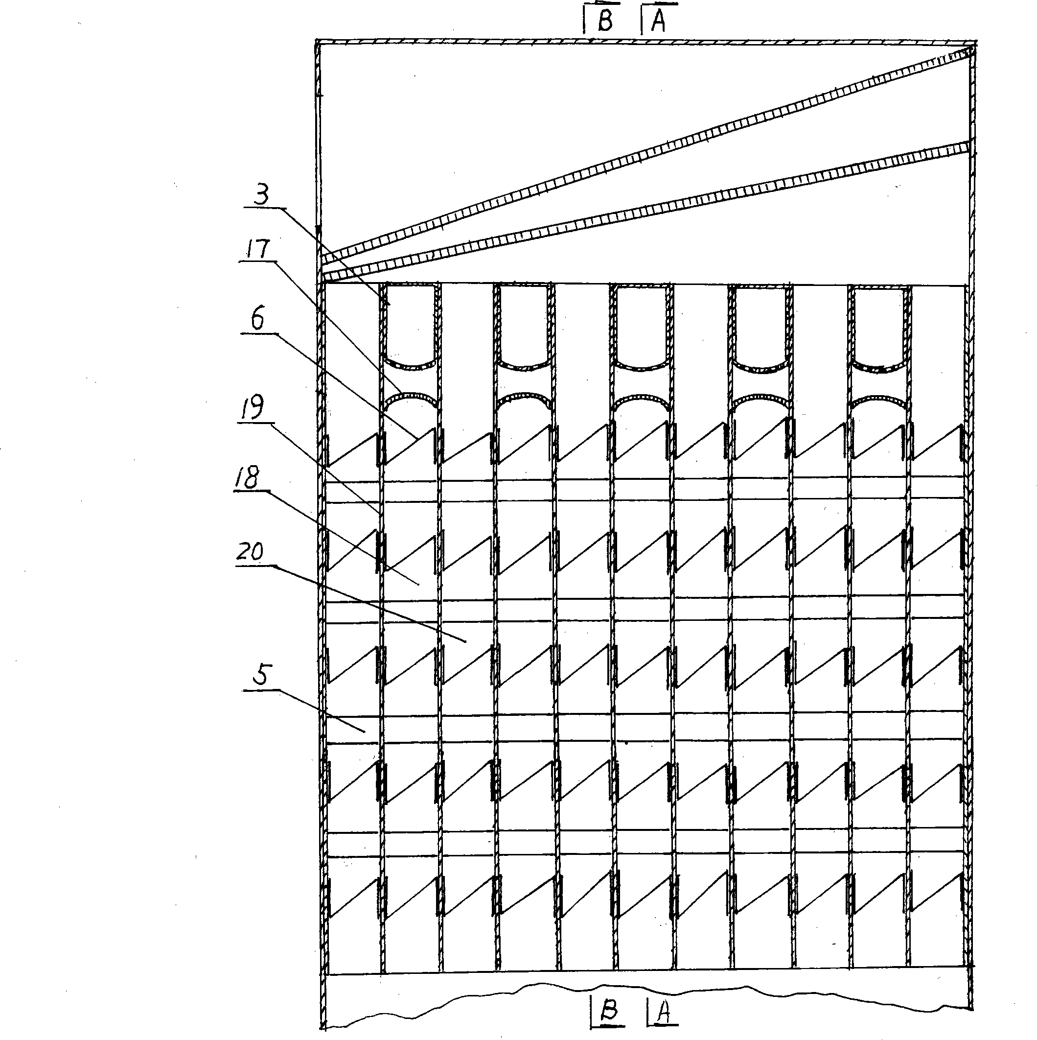
[0011] An improved evaporative refrigeration air conditioner, as shown in Figure 1, Figure 2, and Figure 3, a heat exchanger 2 is installed in the casing 1, and a spray water device is arranged above the heat exchanger 2, and a heat exchanger is located A water reservoir 15 equipped with a water pump 14 is arranged below the device 2, and a metal grid 4 is obliquely installed above the water spray device in the casing 1, and the angle between the metal grid 4 and the horizontal line is 10°-30°, The structure of the heat exchanger 2 is that connecting support columns 5 are evenly distributed in the gaps between the vertically parallel hydrophilic aluminum foil plates 19, and closed support bars 8 are arranged on both sides of the gaps between the hydrophilic aluminum foil plates 19, In the gaps evenly distributed on the top edges of the aluminum foil plates arranged upright and parallel in the heat exchanger 2, a strip-shaped water distribution box with water spray holes evenly ...


PUM


Abstract

The invention discloses an improved evaporative refrigerating air conditioner, wherein, heat exchangers are arranged in a shell; a spray system is arranged on the upper part of the heat exchangers; a water reservoir is arranged under the heat exchangers; the heat exchangers are vertical aluminum foil plates which are parallelly arranged and the gaps among which are uniformly provided with connecting support poles; two sides in each gap are provided with sealing support strips; water distributing boxes sealing top side gaps are arranged at intervals in the gaps uniformly distributed on the topsides; an outlet is respectively arranged on the upper part of one side in each gap the top side of which is sealed, so that the heat exchangers are arranged parallelly at intervals and provided witha dry channel and a wet channel provided with inlets and outlets; metal net braces are respectively uniformly arranged in the dry channel and the wet channel; a metal grid group is arranged in a direct evaporative cooling chamber which is arranged on the lower part of the heat exchangers; the lower part of the direct evaporative cooling chamber is provided with a water outlet which is closed up from a skew wall and communicated with the water reservoir; and an opening position on the lower part of the skew wall is provided with a fan outlet. The air conditioner increases heat exchange area ofthe heat exchangers, improves the evaporating and cooling efficiency, has a compact structure and saves the energy.

Description

technical field [0001] The invention belongs to air conditioning equipment, in particular to an improved evaporative refrigeration air conditioner for providing fresh air indoors. Background technique [0002] The existing evaporative cooling air-conditioning technology is an air-conditioning method that uses water evaporation and heat absorption to reduce the temperature of the air supply and cool down the room. There are many forms of equipment for heat and mass exchange between air and water, mainly direct evaporative cooling air conditioners, indirect evaporative cooling air conditioners, and combinations of the two forms. An air conditioner composed of an indirect evaporative cooling air conditioner and a direct evaporative cooling air conditioner combined in series has a large size and an uncompact structure. There must be at least two induced draft fans, which consume a lot of electric energy. When the air introduced by the induced draft fan passes through the direc...

Claims


Application Information

Patent Timeline
Patent Type & Authority Patents(China)
IPC IPC(8): F24F5/00
Inventor 申泽刚申巧申超
Owner 申泽刚
Why Eureka
Eureka Blog
Learn More