Hot-air stove

A technology of hot air generator and furnace body, which is applied in the direction of furnace grate, air heater, fluid heater, etc. It can solve the problems affecting product quality and grade, hot air is easy to mix with miscellaneous gas, and the ambient air has a large impact, so as to achieve product quality. Guaranteed, improved energy utilization, and reduced production costs

Inactive Publication Date: 2008-11-19
王德金
View PDF0 Cites 9 Cited by
  • Summary
  • Abstract
  • Description
  • Claims
  • Application Information

AI Technical Summary

Problems solved by technology

The disadvantages of this combustion method are: the utilization rate of energy produced by combustion is low, and the use cost is high; there are more solid pollutants...

Method used


Image

  • Hot-air stove
  • Hot-air stove

Examples


Embodiment Construction

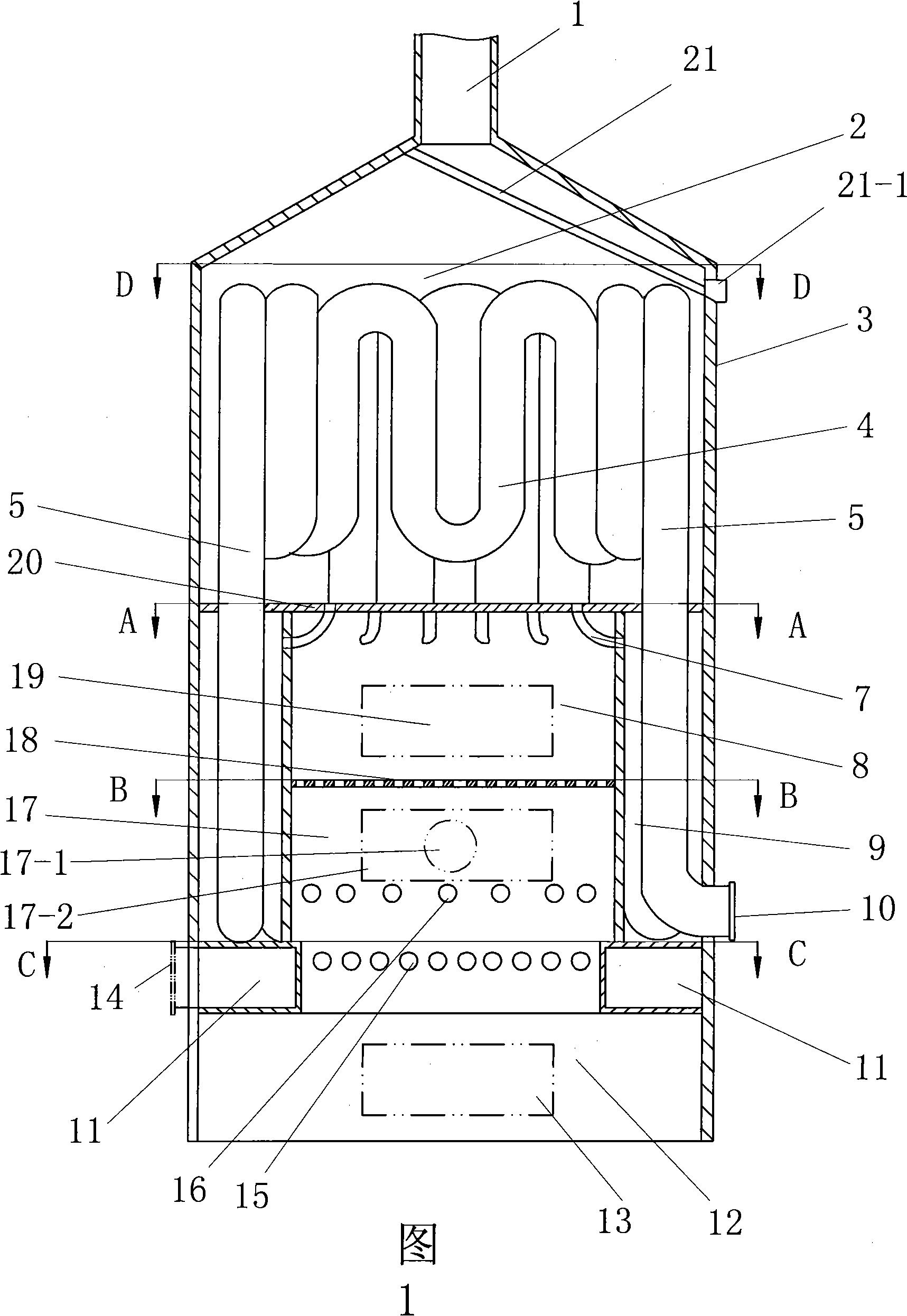
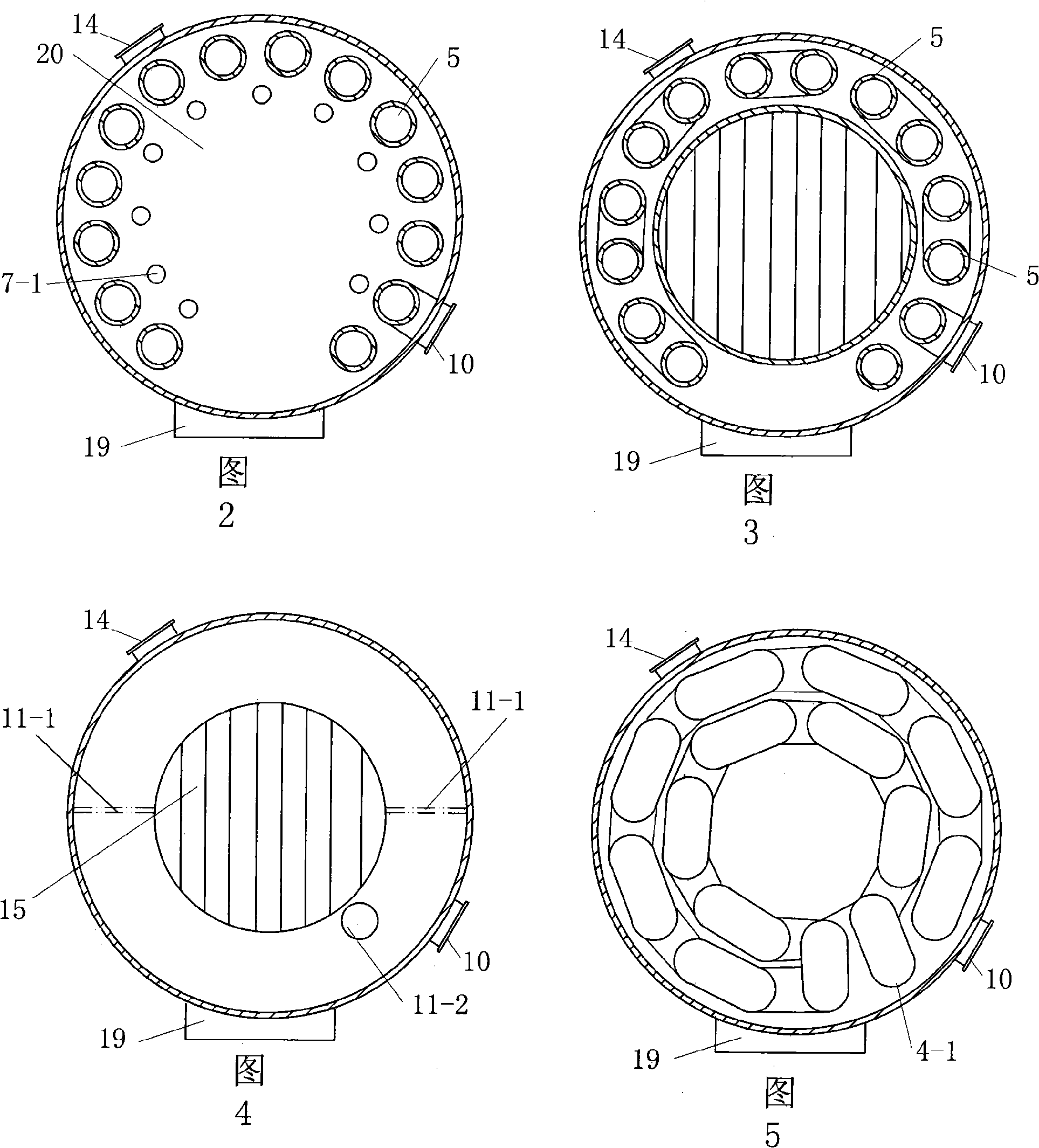
[0021] As shown in the figure, a hot blast furnace includes a furnace body 3 arranged vertically, a chimney 1 is arranged on the top of the furnace body, a combustion chamber 8 is arranged in the center of the furnace body, and heat-absorbing air ducts are arranged around and above the combustion chamber. The inlet 10 of the hot air pipe is located at the side of the furnace and communicates with the outside air; a horizontally arranged top plate 20 is also arranged in the middle of the body of furnace to separate the body of furnace into two parts, the top of the top plate is the heating chamber 2, and the bottom of the top plate is the said The combustion chamber, the lower side of the combustion chamber is provided with a secondary combustion chamber 17 (separated by a grate 18 between the described combustion chamber and the secondary combustion chamber below), and the surrounding walls of the combustion chamber and the secondary combustion chamber are fixed on An airtight ...


PUM


Abstract

The invention relates to a hot blast producer. The technical problem to be solved is to provide a hot blast producer which has the characteristics of high energy utilization rate, clean discharged waste, clean acquired hot blast without smoke smell and low production cost. The invention adopts the technical proposal that: the hot blast producer comprises a chimney on the top and a producer body arranged vertically; the middle of the producer body is provided with a heating chamber and a combustion chamber which are arranged up and down; the combustion chamber and a secondary combustion chamber under the combustion chamber form a closed cylinder body the peripheral wall of which is provided with an air course; a heat absorbing air pipe is arranged zigzag between the heating chamber and the secondary combustion chamber; the peripheral wall of the secondary combustion chamber is also provided with a group of heatconducting holes; the combustion chamber is also provided with a group of syphons, each syphone is respectively communicated with through holes on the peripheral wall and on a top plate; grates on the bottom of the cylinder body consist of hollow pipes, two ends of the hollow pipes are respectively communicated with an annular channel which winds into circles along the peripheral wall of the producer body; and the annular channel is respectively communicated with an inner air pipe outlet and a hot blast outlet.

Description

technical field [0001] The invention relates to a combustion device, in particular to a device for producing hot air by utilizing the heat generated by combustion. Background technique [0002] The hot air generator is the key equipment in the drying device, which is widely used in the drying process of food, agricultural and sideline products and other fields. Although the existing hot blast furnaces have various structural types, the basic combustion methods are the same, that is, the flue gas in the combustion chamber is discharged upwards from the furnace, and the heat generated by combustion heats the air duct, and the outside air absorbs heat through the air duct and becomes hot air. Afterwards, it is used as a source of hot air for people to process. The disadvantages of this combustion method are: the utilization rate of energy produced by combustion is low, and the use cost is high; there are more solid pollutants in the discharged exhaust gas, which has a greater ...

Claims


Application Information

Patent Timeline
IPC IPC(8): F24H3/00F24H9/18F23H3/00F23B60/00
Inventor 王德金
Owner 王德金
Why Eureka
Try Eureka