

Color electrophotographic image forming apparatus
A technology of electrophotography and imaging devices, which is applied in the direction of transmission devices, electrical recording techniques, and electrical recording techniques using charge patterns, etc., which can solve the problems that hinder the miniaturization of imaging devices, and achieve the effects of saving space, low cost, and simplifying the structure
- Summary
- Abstract
- Description
- Claims
- Application Information
AI Technical Summary
Problems solved by technology
Method used
Image

Examples
no. 1 example
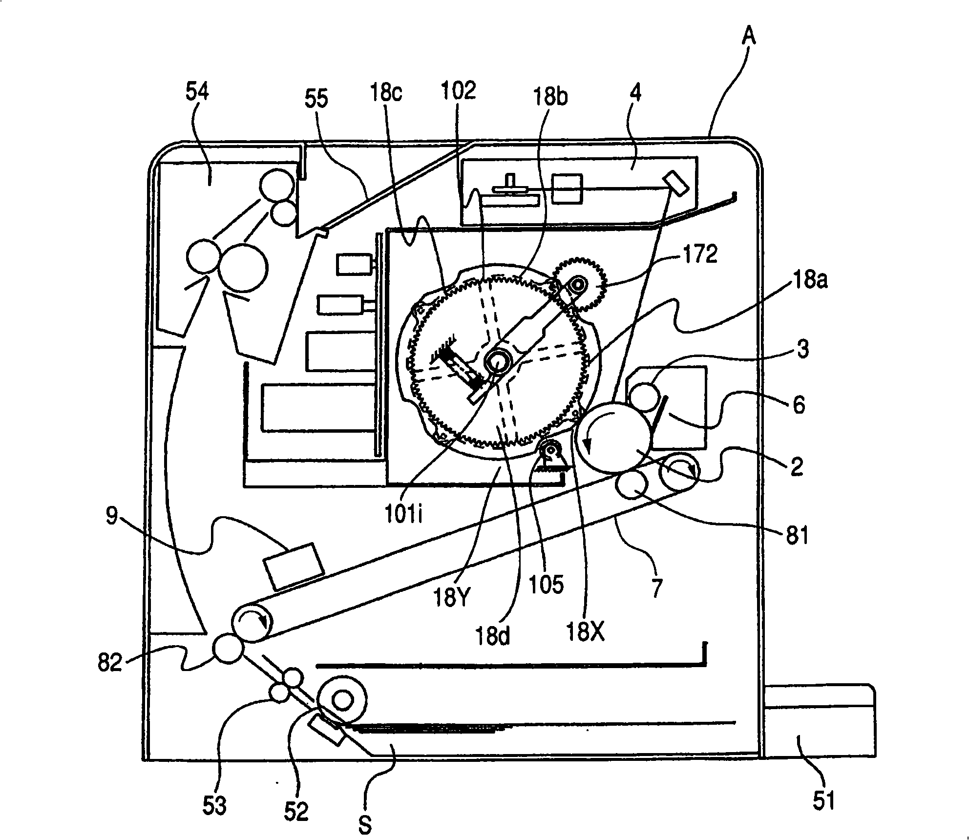
[0035] The color electrophotographic image forming apparatus according to the first embodiment will be described below. In this example, a color laser beam printer having four developing devices is taken as an example of a color electrophotographic image forming apparatus. figure 1 It is a sectional view showing a color laser beam printer.
[0036] First, the image forming operation of the color laser beam printer will be described.
[0037] Such as figure 1 As shown, the image forming apparatus includes an electrophotographic photosensitive drum 2 . A charging roller 3 , an exposure unit 4 , four developing devices 18 a to 18 d , and a cleaning device 6 are provided around the photosensitive drum 2 . The charging roller 3 is charging means for uniformly charging the photosensitive drum 2 . The exposure unit 4 is an exposure device that irradiates the photosensitive drum 2 with a laser beam corresponding to image information. The charged photosensitive drum 2 is irradiate...
no. 2 example
[0083]Next, refer to Figure 7 and 8 Another embodiment of the drive transmission mechanism for rotating the rotating body 102 will be described.
[0084] Figure 7 is a front view showing the configuration of the drive transmission mechanism in which the developing roller 182 a is located at a developing position facing the photosensitive drum 2 . Figure 8 is from the right Figure 7 right side view of . Figure 7 Not indicated Figure 8 The main frame 171 shown in. in addition, Figure 8 Not indicated Figure 7 The transfer belt 7 and the transfer roller 81 are shown in .
[0085] In this embodiment, a cam 183 as a rotating member (guide) rotating together with the rotating body 102 is provided in each of the developing devices 18 a to 18 d supported by the rotating body 102 . Other configurations and operations are the same as the above embodiment.
[0086] Such as Figure 7 and 8 As shown, each of the developing devices 18a to 18d includes contact portions 183...
no. 3 example
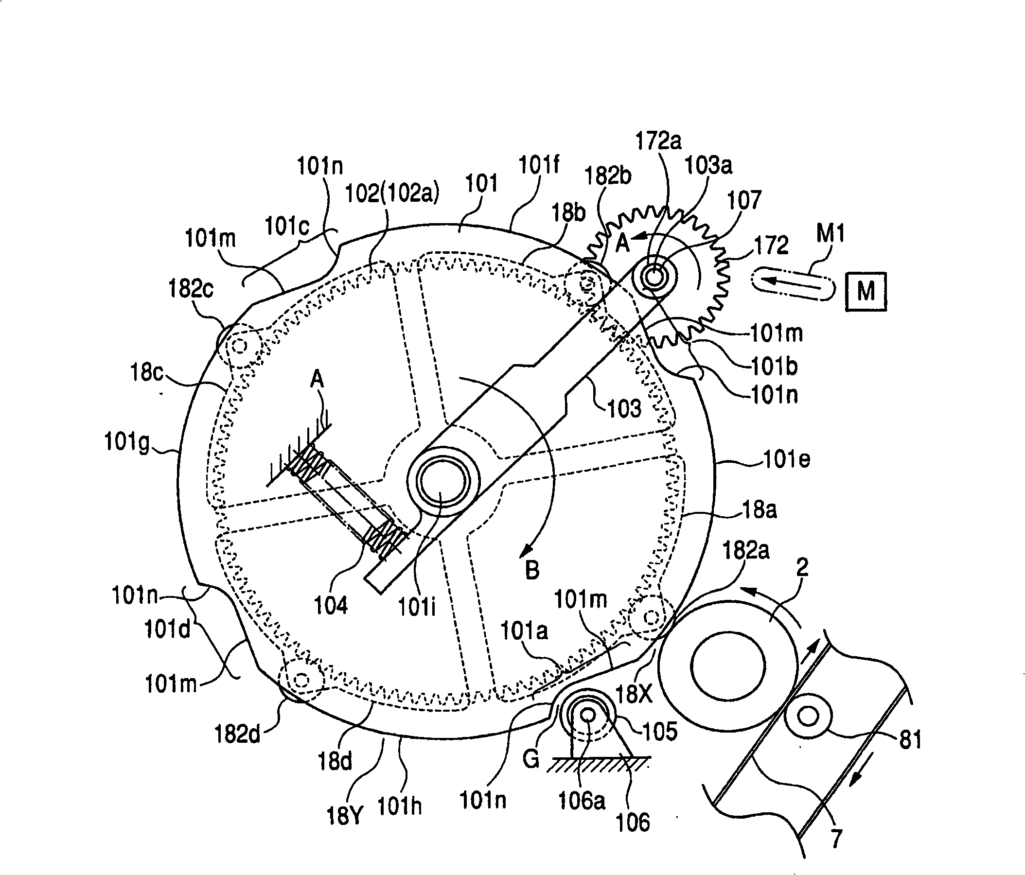
[0090] Next, refer to Figure 9 and 10 Another embodiment of the drive transmission mechanism for rotating the rotating body 102 will be described in detail.
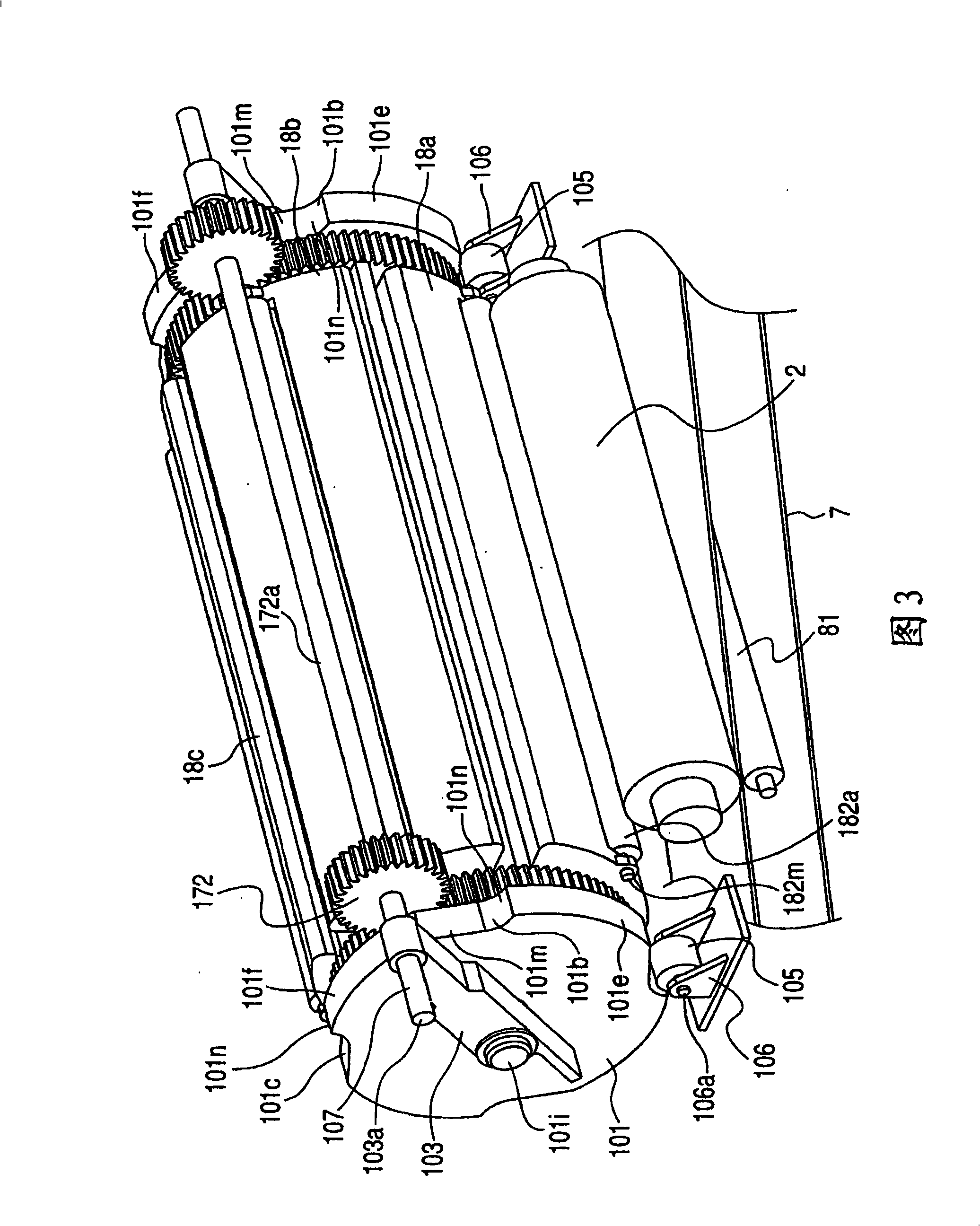
[0091] Figure 9 is a front view showing the configuration of the drive transmission mechanism in which the developing roller 182 a is located at a developing position facing the photosensitive drum 2 . Figure 10 is from the right Figure 9 right side view of . Figure 9 Not indicated Figure 10 The main frame 171 shown in. in addition, Figure 10 Not indicated Figure 9 The transfer belt 7 and the transfer roller 81 are shown in .
[0092] In this embodiment, the above-mentioned regulating member is integrally formed with the photosensitive drum 2 . That is, the support bar 2a for supporting the photosensitive drum 2 also serves as an adjustment member for adjusting the pivotal movement of the rotary body. In this embodiment, the support bar 2a has the function of the adjustment rotary member 105 in the abov...
PUM
 Abstract
Description
Claims
Application Information