Heat sink and method of making same

A heat sink and heat sink technology, which is applied in indirect heat exchangers, cooling/ventilation/heating transformation, heat exchange equipment, etc., can solve the problems of poor assembly workability, inability to manage heat sink assembly schedules, and high assembly costs, and achieve manufacturing simple effect

Inactive Publication Date: 2008-11-19
HITACHI CABLE MEC TECH LTD
View PDF1 Cites 11 Cited by
  • Summary
  • Abstract
  • Description
  • Claims
  • Application Information

AI Technical Summary

Problems solved by technology

[0005] However, the existing heat sinks 111a, 111b are all composed of single fins, which has the problem of high assembly cost
[0006] In addition, in the conventional heat sinks 111a, 111b, if the thickness of the individual heat sinks 112, 115 is made relatively thin, there is also a problem of poor assembly workability.
[0007] Furthermore, the existing heat sinks 111a, 111b require a certain degree of thickness for the individual cooling fins 112, 115, but there is a problem of light weight.
[0008] As a common problem of the two heat sinks 111a and 111b, there are problems such as that it takes time to assemble each heat sink according to the number of heat sinks, and it is impossible to manage the progress of assembling the heat sink every time.

Method used


Image

  • Heat sink and method of making same
  • Heat sink and method of making same
  • Heat sink and method of making same

Examples


Embodiment Construction

[0031] Hereinafter, preferred embodiments of the present invention will be described with reference to the drawings.

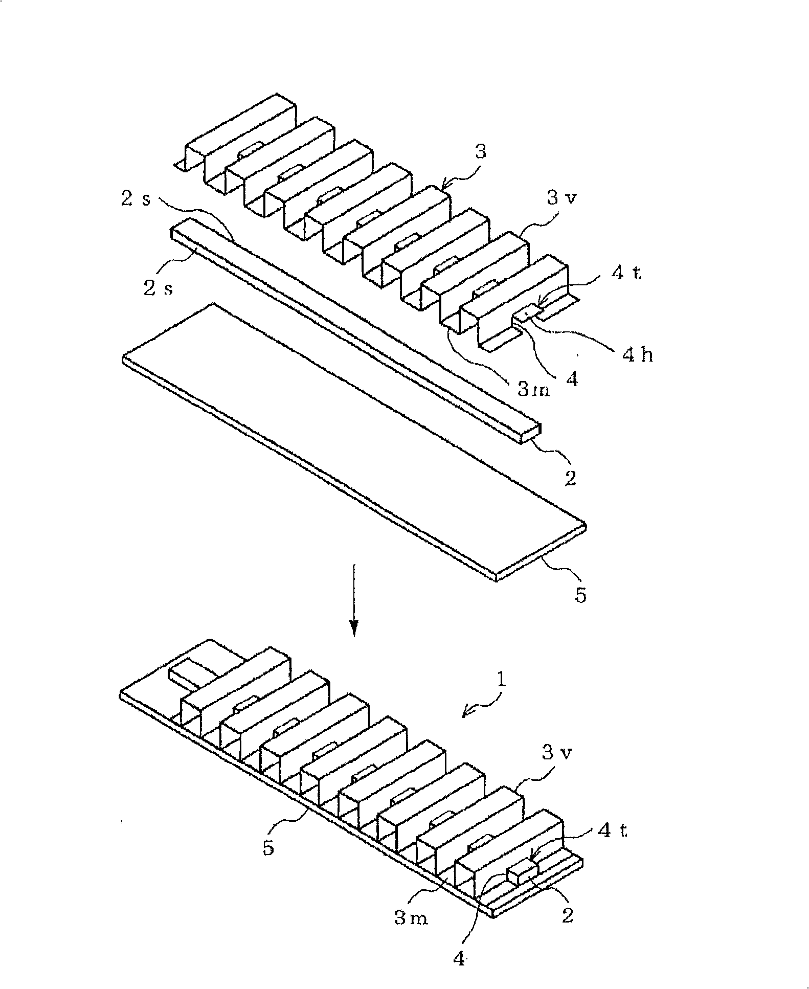
[0032] figure 1 It is a perspective view which shows the heat sink which concerns on the preferred 1st Embodiment of this invention.

[0033] Such as figure 1 As shown, the radiator 1 related to the first embodiment includes: enclosing the working fluid and moving from the heat source to the direction of heat dissipation ( figure 1 In the middle is the heat pipe 2 extending a predetermined length from left obliquely upward to right obliquely downward;

[0034] The heat pipe 2 encloses a working fluid such as water or alcohol in a metal tube made of highly heat-dissipating Cu or the like, and transfers heat by utilizing a phase change such as evaporation or condensation of the working fluid. Since the working fluid is sealed under reduced pressure, the phase change is caused by a very small temperature difference, and the heat is transmitted by steam at a...


PUM


Abstract

The invention provides a thin and light radiator with good assembly operation performance using parts in mass production, capable of effectively and adequately using heat conduction area with low cost, comprising: a heat pipe (2) of which a working fluid is filled and which is extended by a predetermined length from a heat source in a heat radiation direction; and a radiation fin (3) having a mountain portion (3m) and a valley portion (3v) formed in a longitudinal direction of the heat pipe (2), the mountain portion and the valley portion form a continuous waveform. The radiation fin further has a step portion (4) for fitting and retaining the heat pipe (2).

Description

technical field [0001] The present invention relates to a heat sink which is thin and light and has high thermal transferability as a heat dissipation component of electronic equipment and a manufacturing method thereof. Background technique [0002] A radiator is a device that releases heat generated by a heat source to suppress the temperature rise of the heat source. Generally, a heat sink made of an aluminum plate or a copper plate is provided with a heat pipe filled with a working fluid. [0003] For example, Figure 11 The existing radiator 111a shown in (a) is provided with heat pipe joint grooves 113 respectively on a plurality of single (individual) heat sinks 112 formed by a U-shaped shape in transverse cross section, and on these heat pipe joint grooves 113 The heat pipe 114 is joined (for example, refer to Patent Document 1 (Patent No. 3413151) and Patent Document 2 (Patent No. 3413152)). [0004] Figure 11 The conventional heat sink 111b shown in (b) is a devi...

Claims


Application Information

Patent Timeline
Patent Type & Authority Applications(China)
IPC IPC(8): H05K7/20H01L23/36H01L23/427F28D15/02B21D53/02
CPCY10T29/53113F28F1/126H01L23/3672H01L2924/0002H01L23/427F28D15/0233F28F3/025H01L2924/00
Inventor 鹭史彦村山正美加藤木纯一
Owner HITACHI CABLE MEC TECH LTD
Why Eureka
Try Eureka