Method and device for adhering components to a composite molding

A technology for molding parts and components is applied in the field of equipment for producing the composite molding parts, which can solve the problem of high investment, achieve high efficiency and improve the effect of dipping

Inactive Publication Date: 2008-11-19
ALUMINUM CO OF AMERICA
View PDF0 Cites 8 Cited by
  • Summary
  • Abstract
  • Description
  • Claims
  • Application Information

AI Technical Summary

Problems solved by technology

The larger the size of the molded part to be produced, the higher the investment

Method used


Image

  • Method and device for adhering components to a composite molding
  • Method and device for adhering components to a composite molding
  • Method and device for adhering components to a composite molding

Examples


Embodiment Construction

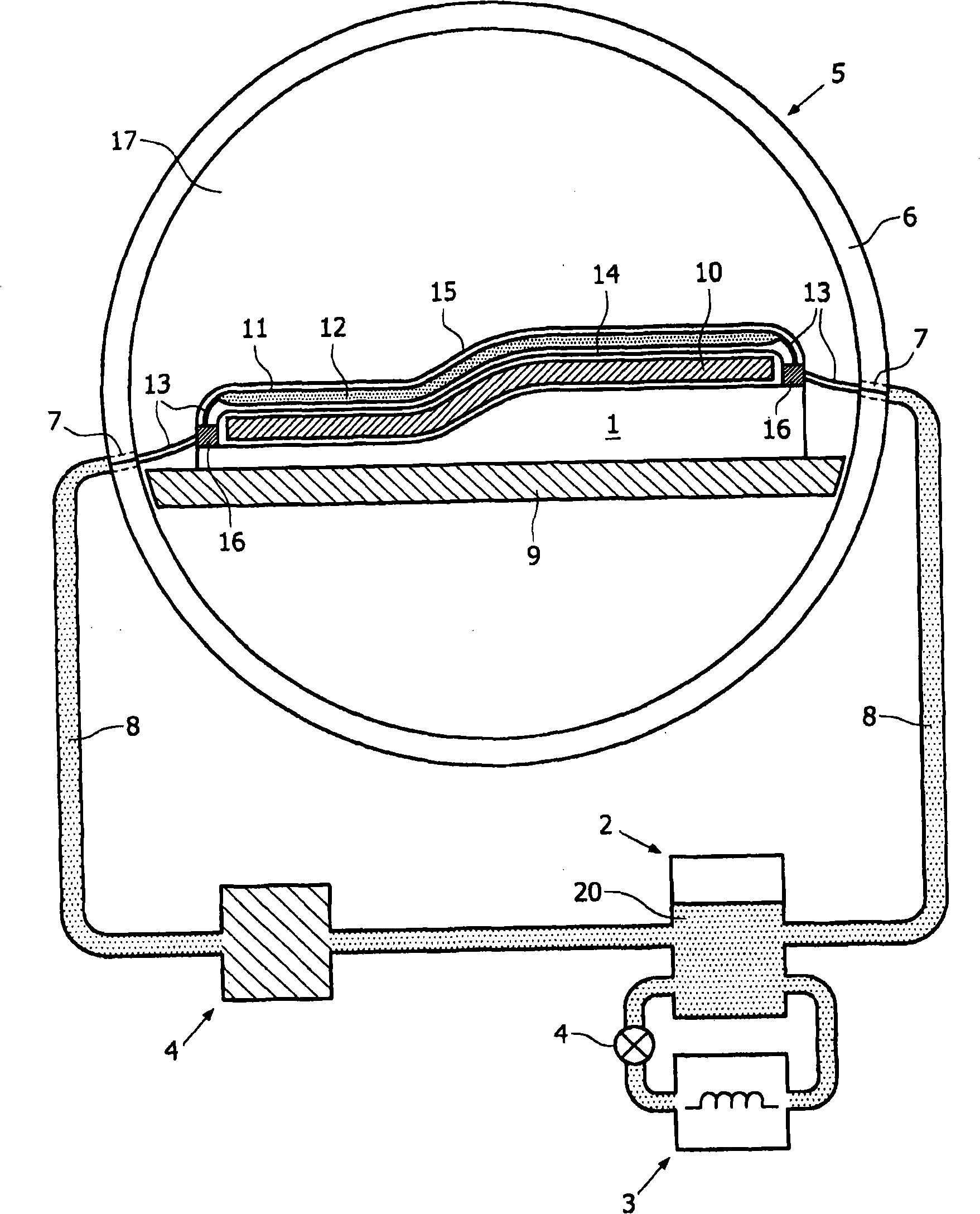
[0033] see figure 1 , the apparatus according to one embodiment of the invention comprises at least: a forming die 1 to which a laminate 10 made of a layer of fiber reinforced material can be attached; a liquid source or liquid tank 2 and a means for bringing the liquid 20 to A device 3 for the first temperature; a heating device 11 attachable to the laminate 10, said heating device having at least one cavity 12 and connection means 13 connected to the cavity for supplying and discharging liquid; and for making The liquid 20 flows through the pumping device 4 of the at least one cavity 12 . In the embodiment shown, the whole structure is incorporated in a pressure vessel or autoclave 5 having a wall 6 through which a pipe 8 for a liquid 20 is attached via an access opening 7 . The pressure vessel 5 is resistant to typical pressures which are common in the production of molded parts made of fiber-reinforced plastic, for example an internal pressure of at least 10 bar. The for...


PUM


Abstract

The invention relates to a method for adhering components to a composite molding. The method comprises: stacking the components provided with an appropriate bonding matter; positioning a heating device provided with at least one cavity (12), over at least a section of the stacking component; and passing a medium brought to a first temperature through the at least one cavity of the heating device, whereby the stacking component is brought at least partially to the first temperature, and each component is interconnected to the molding. The invention also relates to a device for implementing the method and a heatable membrane that can be applied in the method.

Description

technical field [0001] The invention relates to a method for bonding components to composite molded parts. The invention also relates to an apparatus for producing the composite molding. Background technique [0002] In industry, especially in the aircraft industry, methods of bonding components such as fuselage components, airfoils and reinforcements to composite moldings are often used, for example with thermosetting adhesives. For this purpose, the parts to be bonded are provided with an adhesive layer and then joined to each other. Bonding between the parts is achieved by bringing the thermosetting bonding substance to a first elevated temperature to cure the thermosetting bonding substance. In particular, it is important to remove as much air as possible between the parts and / or in the adhesive layer, as this enables the desired good bond between the parts to be achieved. Therefore, a known method consists in keeping the component within a vacuum-tight membrane, wher...

Claims


Application Information

Patent Timeline
IPC IPC(8): B29C65/26B29C65/48B29C33/04B29C33/40B29C70/44B29C70/46
CPCY10T156/1043B29C65/48B29C70/46B29C65/4835B29C65/4815B29C66/91411B29C70/44B29C66/91423B29C66/9141B29C66/91B29C65/26B29C33/405B29C66/47B29C66/472B29C66/81455B29C33/04B29C66/91431B29C66/7212B29C66/7392B29C66/7394B29C66/71B29C65/18B29C66/8322B29C66/73751B29C66/73161B29K2307/04B29K2077/00B29K2309/08B29K2075/00B29K2067/003B29K2067/006B29K2071/00B29K2081/06B29K2081/04B29K2079/08B29K2055/02B29K2305/00B29K2023/06B29K2023/12B29K2069/00B29K2071/12
Inventor G·H·J·J·罗布罗克斯E·J·克龙
Owner ALUMINUM CO OF AMERICA
Why Eureka
Try Eureka