Supercharge Your Innovation With Domain-Expert AI Agents!

Synthetic aperture radar

A synthetic aperture radar, radar technology, applied in the direction of reflection/re-radiation of radio waves, utilization of re-radiation, measurement devices, etc., can solve problems such as increasing signal processing overhead and introducing blind spots.

Inactive Publication Date: 2008-11-19
ASTRIUM GMBH
View PDF1 Cites 10 Cited by
  • Summary
  • Abstract
  • Description
  • Claims
  • Application Information

AI Technical Summary

Problems solved by technology

However, this is a complex solution, requires increased signal processing overhead, and has the potential to introduce dead zones in the image, which are related to the high PRF pulse transmission causing saturation in the receive chain (or avoiding it by blanking)

Method used


Image

  • Synthetic aperture radar
  • Synthetic aperture radar
  • Synthetic aperture radar

Examples


Embodiment Construction

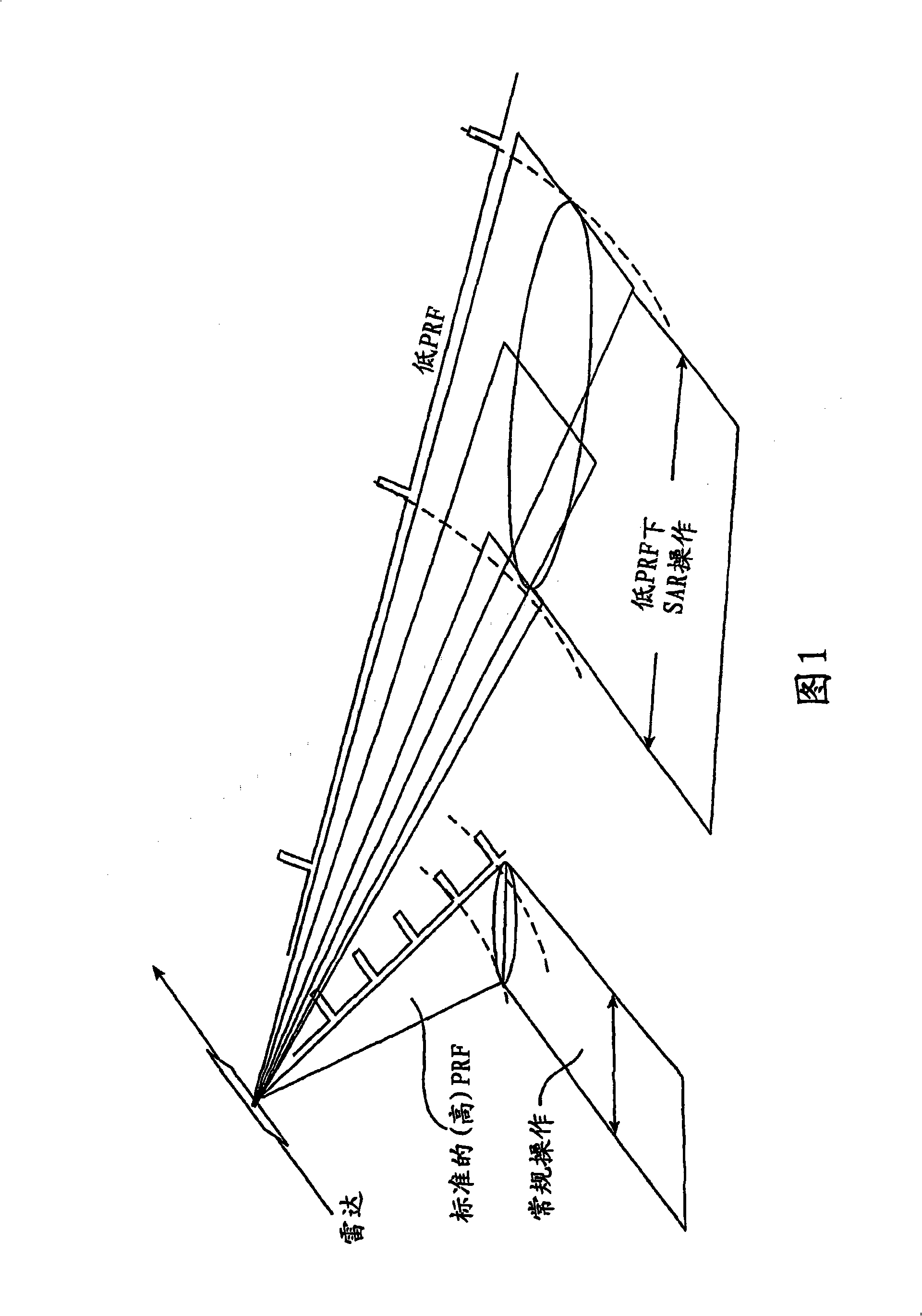
[0029] Low PRF mode situations are uncommon in the context of SAR work, given their tolerance to highly ambiguous azimuth impulse response functions. This will lead to the introduction of highly cluttered echo signals in targets containing resolution cells.

[0030] When operating in this mode, the form of the azimuth impulse response function is significantly different from what is conveniently referred to as "conventional" SAR operation. Here, during a given observation sequence, the radar operates in the usual high PRF mode associated with the normal SAR mode, and the azimuth impulse response function is pre-occupied by a single main lobe surrounded by side lobes of small amplitude. When operating in these "regular" modes, the grating lobes are still present, but with very small amplitudes.

[0031] Azimuth IRF in low PRF mode

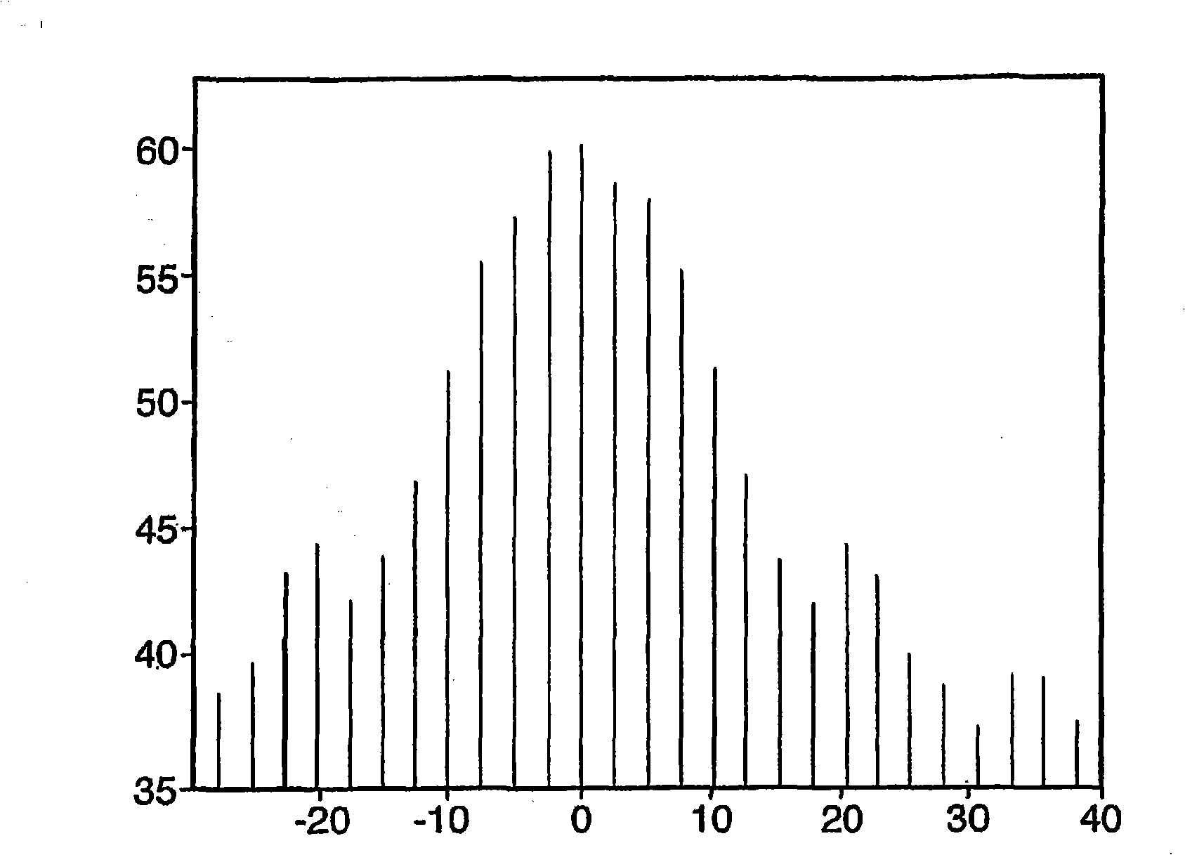
[0032] A typical azimuthal IRF profile when operating in low PRF mode is image 3 shown. In this grating lobe array, the main lobe is desired...


PUM


Abstract

A method of operating synthetic aperture radar in a low PRF mode, comprising generating a stream of radar pulses, imposing onto said stream a predetermined modulation of the Pulse Repetition Frequency (PRF), directing said stream to a target area, and processing received pulses, comprising separating the received pulses as a sequence of sets, and superposing received radar pulses of said sets, whereby to enhance the central received lobe and to attenuate side lobes.

Description

technical field [0001] The present invention relates to synthetic aperture radar (SAR). Background technique [0002] A common requirement for SAR is to detect relatively small targets, eg, a ship in the ocean, in a generally feature-less area. In this case, the radar footprint is expected to have a wide swath in the "cross track" direction at right angles to the "along radar platform track" direction in order to scan as large an area as possible. As will be explained below, and as shown in Figure 1, a wide swath requires a low pulse repetition frequency (PRF). Operating SAR at low PRF may introduce ambiguity in the "along radar platform track" direction. They are "phantom" images induced in adjacent lobes, and are similar to the grating lobes produced when monochromatic light is projected onto a rough diffraction grating. [0003] When operating in SAR mode, the radar is generally required to transmit pulses at a high enough rate (see Figure 1) while sampling along the t...

Claims


Application Information

Patent Timeline
Patent Type & Authority Applications(China)
IPC IPC(8): G01S13/90G01S13/22G01S7/292
CPCG01S7/2926G01S13/22G01S13/90G01S13/904G01S13/9054G01S13/9056
Inventor D·兰卡施里C·霍尔
Owner ASTRIUM GMBH
Features
  • R&D
  • Intellectual Property
  • Life Sciences
  • Materials
  • Tech Scout
  • Unparalleled Data Quality
  • Higher Quality Content
  • 60% Fewer Hallucinations
Learn More