Double-cutterhead dynamic cutter tower seat structure

A technology of turret base and double cutter head, which is applied in the direction of tool holders, large fixed members, metal processing machinery parts, etc., can solve the problems of large space occupation, high cost, damage to tools and machine tables, etc., and achieve machine The effect of streamlining equipment and saving costs

Inactive Publication Date: 2008-11-26
FACTORY AUTOMATION TECH CO LTD
View PDF2 Cites 7 Cited by
  • Summary
  • Abstract
  • Description
  • Claims
  • Application Information

AI Technical Summary

Problems solved by technology

[0008] 1. The setting of two power sources is relatively expensive in production
[0009] 2. The setting of the two power sources takes up a larger space than the overall volume
[0011] 4. The wheelbase is too short and too clo

Method used


Image

  • Double-cutterhead dynamic cutter tower seat structure
  • Double-cutterhead dynamic cutter tower seat structure
  • Double-cutterhead dynamic cutter tower seat structure

Examples


Embodiment Construction

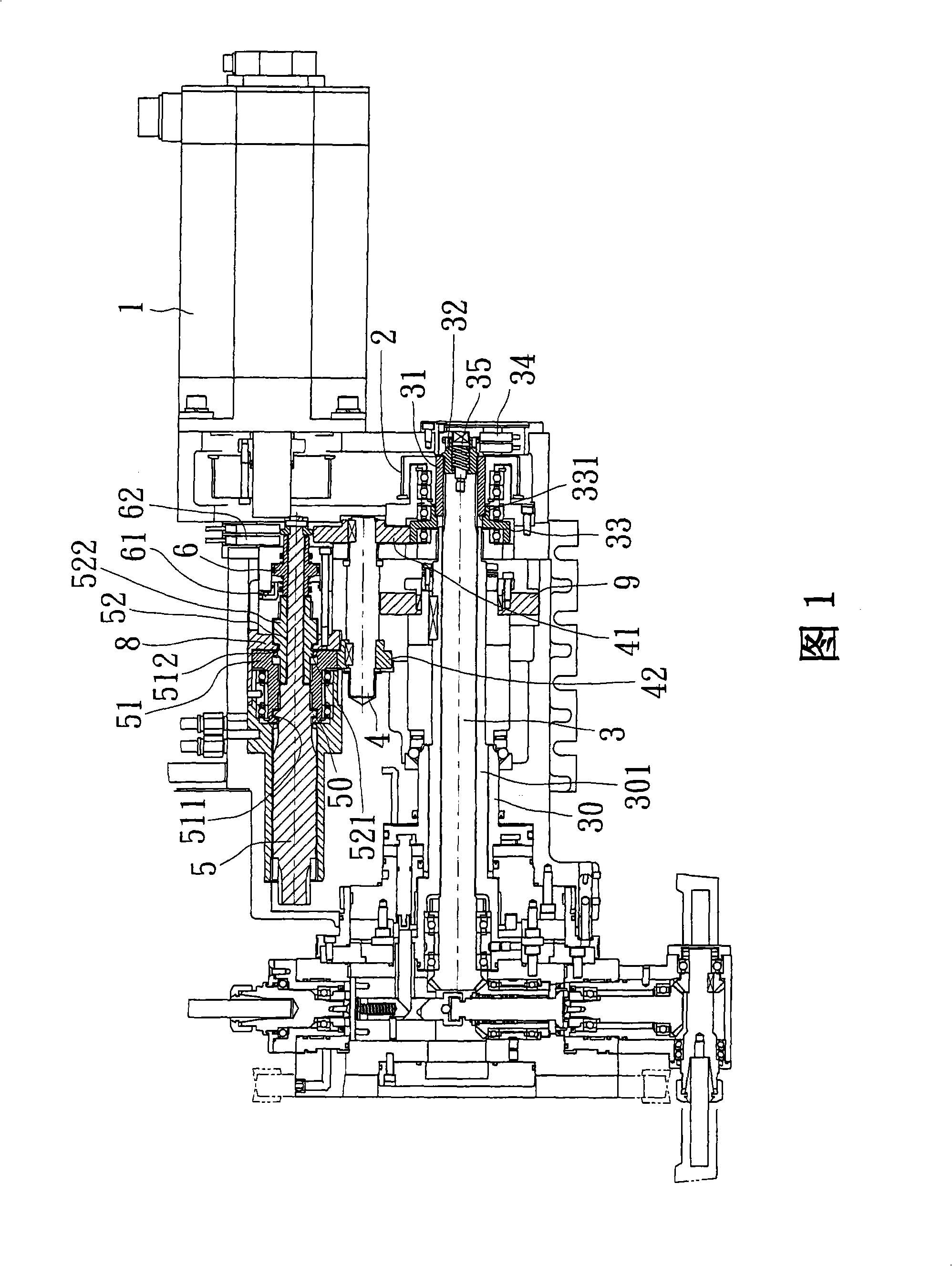
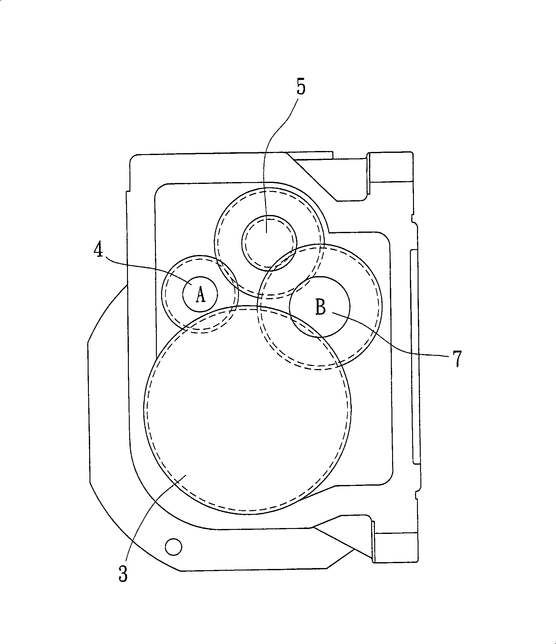
[0049] First of all, please refer to Figure 1, which is a schematic cross-sectional view of the overall structure of a double-blade power turret seat of the present invention. The main power source 1 on the machine transmits power to the power group 2, and the power group 2 is linked. The gear ring 31 outside the main shaft 3 transmits the power to the A shaft 4, and the tooth seat 42 of the A shaft 4 transmits the power to the transmission part 51 on the inner knife shaft 5, and the transmission part 51 cooperates with the piston clutch part 6 to select The inner and outer cutterheads of the inner cutter shaft 5 and the B shaft 7 are driven to rotate separately for tool selection operation and processing (please refer to figure 2 shown]; where:

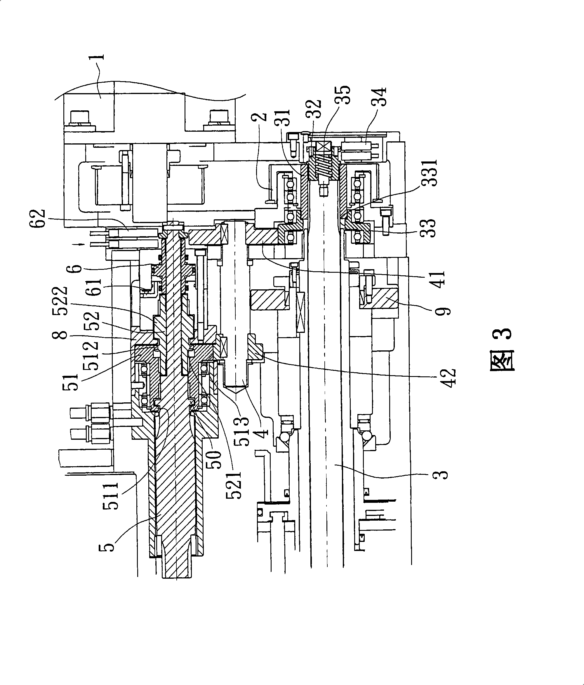
[0050]Please also refer to Fig. 3, there is a clutch seat 32 at the end of the main shaft 3, the clutch seat 32 can move to push the displacement of the gear ring 31 of the main shaft 3, and an external rotation is provided on the ou...


PUM


Abstract

The invention discloses a dual-cutter head drive cutter tower support structure. A main power source is arranged in a machine set, when the single power source is adopted to start the processing of a main shaft or push a cutter head for selecting cutters through a power unit, a consecutive transmission component going through the main power source and a piston clutch respectively drive a rotary shaft A or B to cause the power to do selective transmission through the rotary shaft A to drive an inner cutter head for movably selecting cutters or transmit the power through the rotary shaft B to drive an outer cutter head for cutter selection, thereby, the structure of the single drive power of the invention can have the main shaft move (the original movement of the main shaft and the power transmission unchanged) or the inner cutter disc or the outer cutter disc to select cutters, thus simplifying the equipment of machine set and saving costs.

Description

technical field [0001] The invention relates to a double-cutter power tool turret structure, which uses a single power source to drive a main shaft, drive a power tool seat, or select inner and outer tool discs to rotate for tool selection. Background technique [0002] The inventor applied for the turret seat structure of the double turret with No. 200410033934.1 before the Chinese patent. The power is transmitted to the outer gear ring or the central shaft by the power switching device, so that the inner and outer turrets can be driven and rotated separately for tool selection. Operation, so that it can be processed as a processing machine; characterized in that: [0003] The power switching device is composed of a power source, a rotary sleeve, a transmission shaft and a transmission sleeve; the power source is a servo motor, and its output shaft is fixed with a bevel gear that can mesh with the bevel gear on the rotary sleeve. The sleeve is equipped with a transmission ...

Claims


Application Information

Patent Timeline
IPC IPC(8): B23B29/32B23Q1/25
Inventor 卢永祥林炳铄
Owner FACTORY AUTOMATION TECH CO LTD
Why Eureka
Try Eureka