Hermetic compressor

A closed compressor and cylinder bore technology, which is applied in compressors, liquid displacement machinery, refrigerators, etc., can solve the problems of low efficiency, reduced volumetric efficiency, increased clearance volume and re-expansion loss of closed compressors And other issues

Inactive Publication Date: 2008-11-26
PANASONIC CORP
View PDF1 Cites 4 Cited by
  • Summary
  • Abstract
  • Description
  • Claims
  • Application Information

AI Technical Summary

Problems solved by technology

Increased clearance volume increases re-expansion losses, which reduces volumetric efficiency and therefore reduces refrigerant flow
As a result, hermetic compressors do not have sufficient efficiency

Method used


Image

  • Hermetic compressor
  • Hermetic compressor
  • Hermetic compressor

Examples


Embodiment

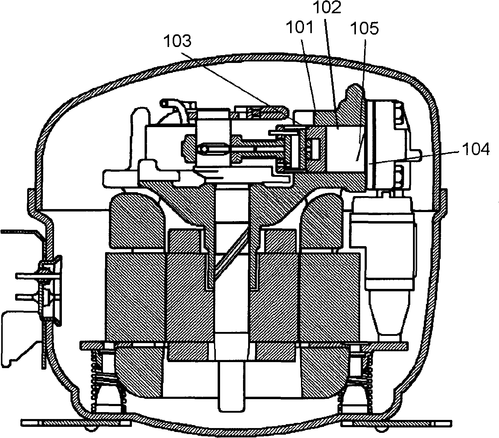
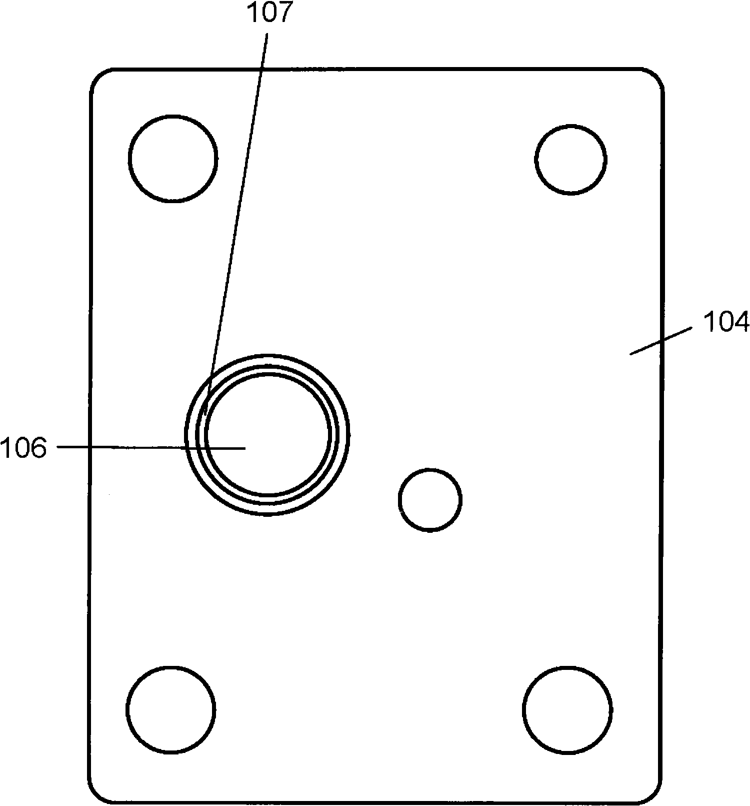
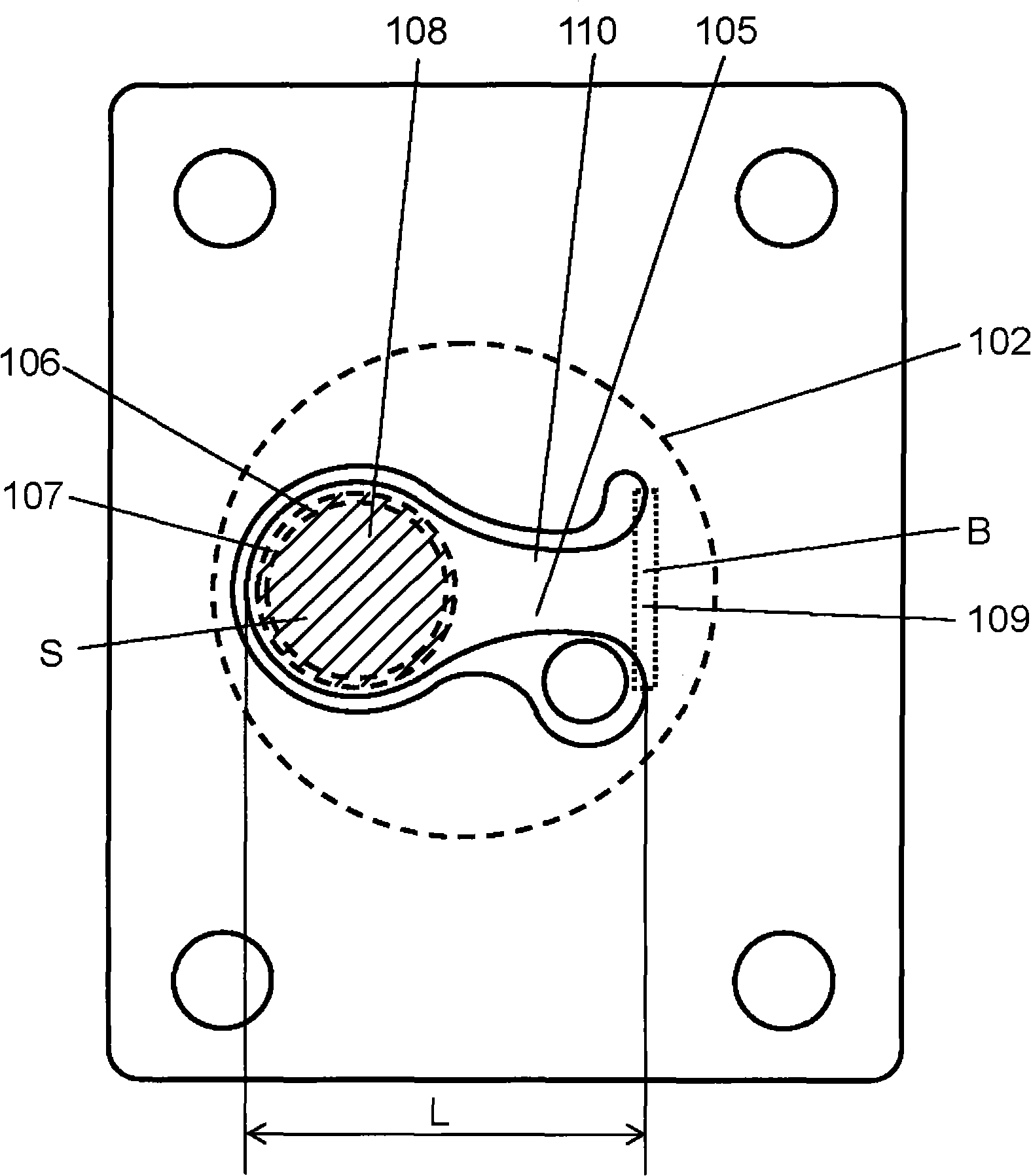
[0024] figure 1 is a sectional view of the hermetic compressor according to the embodiment of the present invention. figure 2 is a schematic diagram of the valve plate of the hermetic compressor. image 3 is a schematic diagram of the suction reed of the hermetic compressor. Figure 4 It is a schematic side view of the suction reed. Figure 5 is a graph showing volumetric efficiency and the ratio of the length between the support end of the suction reed and the end on the opening / closing portion side to the area within the circumference of the suction valve seat of the suction reed. Image 6 It is a graph showing the measurement results of the volumetric efficiency and the area within the circumference of the suction valve seat of the suction reed. Figure 7 It is a graph showing the volumetric efficiency of the hermetic compressor and the measurement results of the length between the support end of the suction reed and the end on the opening / closing portion side.

[002...


PUM


Abstract

The inclination of the suction reed at the time of sucking the refrigerant can be increased when L / S is not more than 0.25 where S (mm2) represents the area within the periphery of the suction valve seat of the suction reed, and L (mm) represents the length between the support end and the tip on the opening / closing part side of the suction reed. The increased inclination of the suction reed smoothes the flow of the refrigerant into the cylinder bore from the inside of the suction valve seat so as to reduce the suction resistance and the clearance volume, thereby reducing the re-expansion loss. As a result, the refrigerant flow is increased to increase the volumetric efficiency, thereby improving the freezing performance of the hermetic compressor.

Description

technical field [0001] The present invention relates to a hermetic compressor for a refrigerator. Background technique [0002] Some conventional high-efficiency hermetic compressors, such as those disclosed in Japanese Patent Laid-Open Publication No. H09-072280, have multiple suction ports to reduce the total suction resistance. [0003] A conventional hermetic compressor will be described below with reference to the accompanying drawings. Figure 8 It is a sectional view of the hermetic compressor of the said patent document 1. Figure 9 is a schematic diagram of the valve plate of the hermetic compressor. Figure 10 is a schematic diagram of the suction reed of the hermetic compressor. [0004] Such as Figure 8 As shown, the hermetic compressor includes a cylinder 401 having a cylinder bore 402 in which a piston 403 reciprocates. The cylinder bore 402 has a valve plate 404 at its open end to seal the cylinder bore 402 . A suction reed 405 is interposed between the v...

Claims


Application Information

Patent Timeline
Patent Type & Authority Applications(China)
IPC IPC(8): F04B39/10F04B39/02
CPCF04B39/1066Y10T137/85986Y10T137/7893F04B39/1073F04B39/023F16K15/16F25B31/00F16K99/0007F16F1/18F05B2210/14Y10S251/00Y10S251/902Y10S417/902F25B41/20F16K15/161
Inventor 横田和宏渡部究
Owner PANASONIC CORP
Why Eureka
Try Eureka