Electromagnetic valve

A solenoid valve and spool technology, applied in the field of solenoid valves, can solve problems such as inconsistency of fuel injection volume of products, difficulty in adjusting the consistency of solenoid valve air gaps, etc., and achieve reduced induced eddy currents, reduced heat generation, and small volume Effect

Inactive Publication Date: 2008-12-03
姜禾
View PDF0 Cites 11 Cited by
  • Summary
  • Abstract
  • Description
  • Claims
  • Application Information

AI Technical Summary

Problems solved by technology

Because the axial matching plane between the solenoid core 6 and the armature 9 is concave, it is quite difficult to adjust the consistency of the air gap of the solenoid valve, resulting in the inconsistency of the fuel injection quantity of the product

Method used


Image

  • Electromagnetic valve
  • Electromagnetic valve
  • Electromagnetic valve

Examples


Embodiment Construction

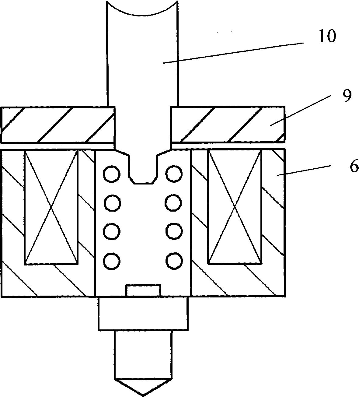
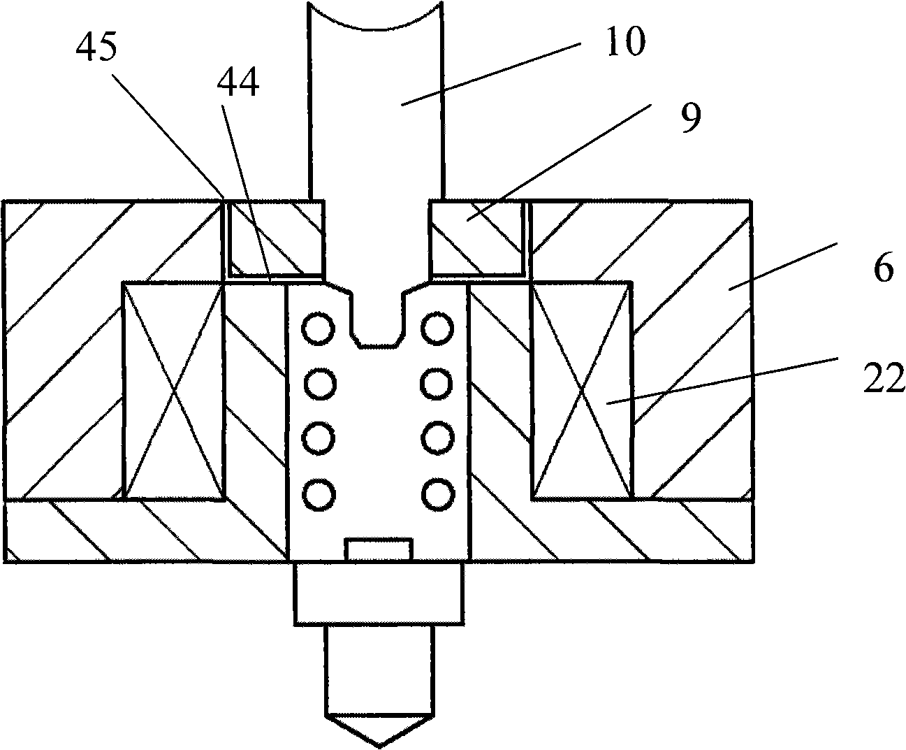
[0028] refer to Figure 8-10 , The solenoid valve of the present invention has a magnetic circuit 25 composed of an iron core 6 , a magnetic ring 8 and an armature 9 . The valve core 10 and the armature 9 are assembled into one body with interference, move together, and are pressurized in the opening direction by the valve spring 7 . The air gap between the armature 9 and the upper surface of the iron core 6 is determined by the axial assembly position of the armature 9 on the valve core 10 .

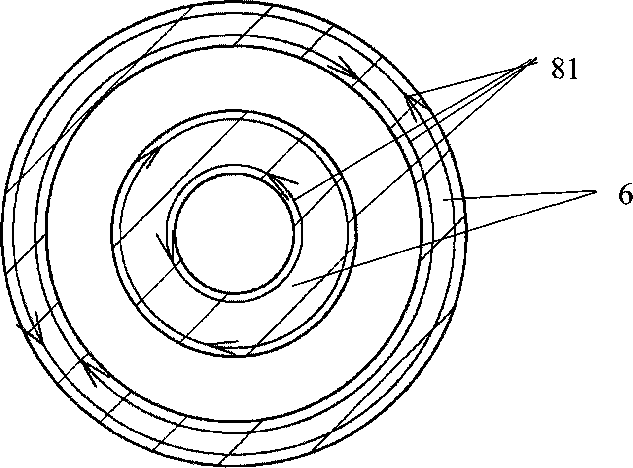
[0029] Such as Figure 8 As shown, the iron core 6 is composed of an electromagnet core 21, a coil winding 22, and a terminal plug 15, and is integrated with potting glue. The electromagnet core 21 is made of solid soft magnetic alloy. Such as Figure 7 As shown, there is a complete gap 91 on one radial side of the electromagnet core 21, and the gap 91 is filled with potting compound.

[0030] Selecting the spring seat 3 with an appropriate installation height ensures that the pres...


PUM


Abstract

The invention relates to a solenoid valve. A magnetic circuit of the solenoid valve comprises a soft magnetic core (6), a magnetic ring (8) and an armature iron (9). The magnetic ring (8) is assembled inside a blind hole of a control valve body (11) in a stationary fit way, the blind hole is concentric with a control valve core, and the armature iron (9) is assembled below the control valve core. Because the inner hole of the magnetic ring (8) is concentric with the outer circumference of the armature iron (9), the concentricity of all the mobile components of the solenoid valve is ensured. The mass of the armature iron (9) is much lower than that of conventional solenoid valve armature irons, so that the response speed of the inventive solenoid valve is faster. The inventive solenoid valve can be used in electrically controlled monoblock pumps, spray nozzles of electrically controlled pumps, and high-pressure common rail oil sprayers.

Description

technical field [0001] The invention relates to an electromagnetic valve, in particular to an electromagnetic control valve used in an electronically controlled fuel injection device for a vehicle engine. Background technique [0002] Traditionally designed solenoid valves used in diesel EFI systems are as follows: figure 1 with figure 2 shown. [0003] figure 1 Shown is a widely used solenoid valve, which is mainly composed of an electromagnet core 6 , an armature 9 and a valve core 10 . figure 1 The main problem of the shown structure is that the armature 9 is bulky, and its projected area is the same as that of the electromagnet core 6 . Due to the large mass of the moving parts composed of the armature 9 and the valve core 10, the dynamic response of this solenoid valve is relatively slow. In addition, the electromagnet iron core 6 is an integral structure, and the induced eddy current in the iron core is stronger during operation, which reduces the energy conversi...

Claims


Application Information

Patent Timeline
Patent Type & Authority Applications(China)
IPC IPC(8): F16K1/00F16K31/06
Inventor 姜禾
Owner 姜禾
Why Eureka
Try Eureka