
Valve core replaceable carbon dioxide refrigerating system throttling valve

A carbon dioxide and refrigeration system technology, which is applied in the field of refrigeration system throttling components and carbon dioxide refrigeration system throttle valves, can solve the problems of high manufacturing cost, poor reliability, and inability to effectively adjust the optimal pressure on the high-pressure side, etc., to achieve economical use cost, the effect of widening the application range

Inactive Publication Date: 2008-12-03
SHANGHAI JIAO TONG UNIV
View PDF1 Cites 6 Cited by
  • Summary
  • Abstract
  • Description
  • Claims
  • Application Information

AI Technical Summary

Problems solved by technology

The structure of the high-pressure control valve in this scheme is very complicated, and there are many types of components and are not general-purpose components. They need to be specially designed, the manufacturing cost is high, and the reliability is not good.
In terms of applicability, the throttling control mechanism cannot effectively adjust the corresponding optimal pressure on the high pressure side when the temperature range of the gas cooler varies greatly
[0005] In addition, commonly used throttling devices are divided into different product series and different specifications in different series to match refrigeration systems with different capacity requirements, that is, when the capacity of the refrigeration system needs to be changed, the entire throttling device must be replaced
[0006] So far, there has not been a transcritical carbon dioxide refrigeration system that uses a new type of temperature sensing element to automatically adjust the optimal pressure of the system for different gas cooler outlet temperatures. It has a simple structure and is easy to disassemble and assemble. Adjustable throttling mechanism to replace part of spool assembly

Method used


Image

  • Valve core replaceable carbon dioxide refrigerating system throttling valve
  • Valve core replaceable carbon dioxide refrigerating system throttling valve
  • Valve core replaceable carbon dioxide refrigerating system throttling valve

Examples


Embodiment Construction

[0017] Specific embodiments of the present invention will be further described below in conjunction with the accompanying drawings.

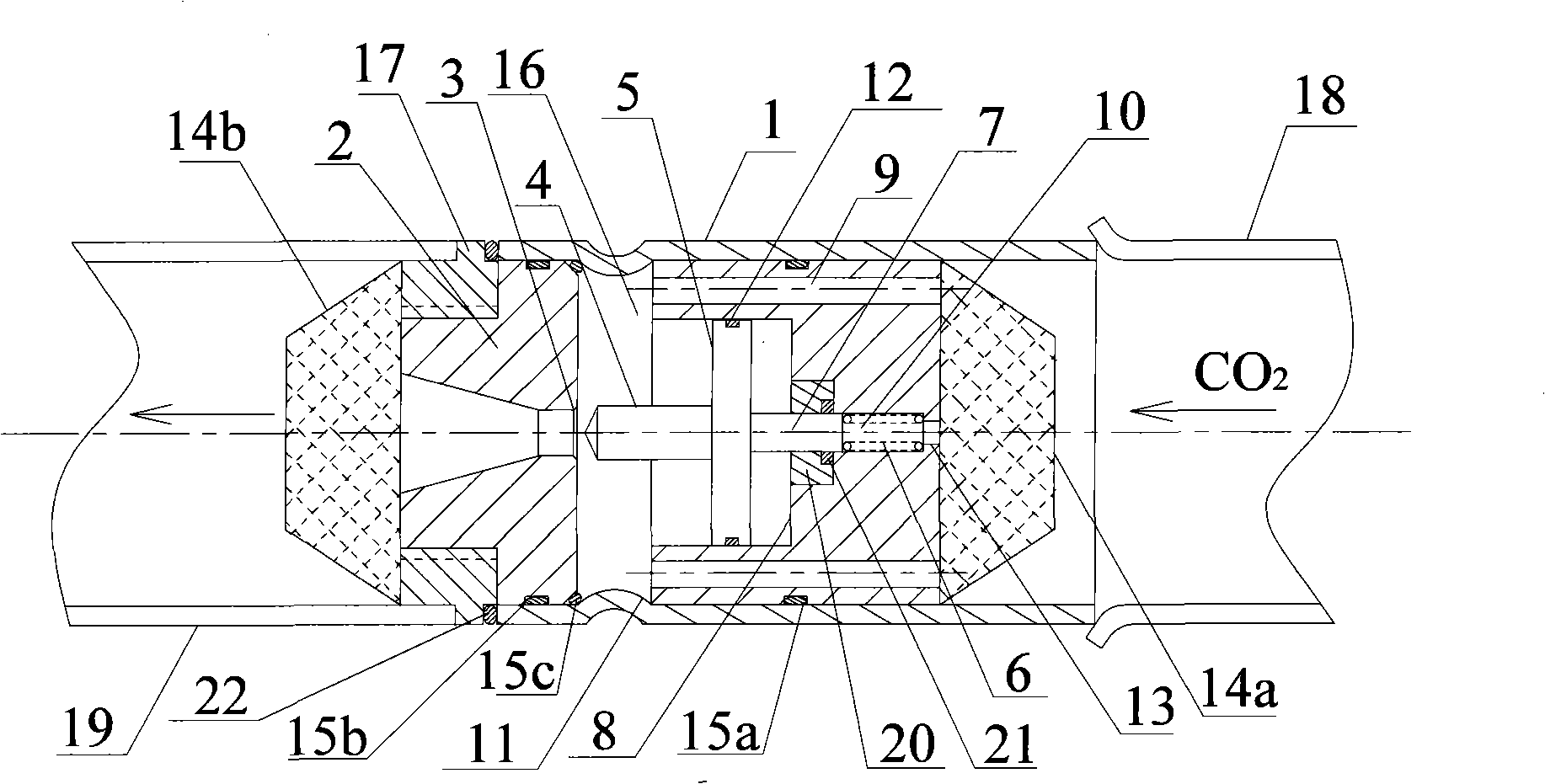
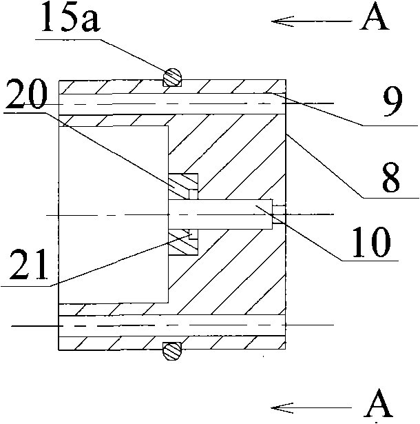
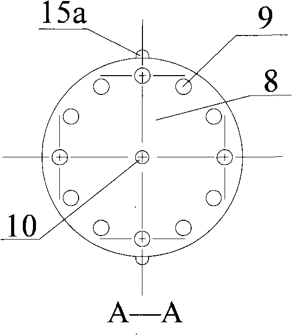
[0018] Such as figure 1 As shown, the present invention includes: casing 1, valve seat 2, valve port 3, valve needle 4, transmission plate 5, memory spring 6, transmission plate connecting rod 7, air intake channel member 8, air intake channel 9, center hole 10. Annular groove 11, air inlet cavity 16, air outlet pipe joint 17, air inlet pipe 18, air outlet pipe 19, sealing block 20.

[0019] An annular groove 11 is formed on the outer circumference by extrusion near the left end of the casing 1, which is used to position the valve seat 2 and the intake passage member 8 at both ends. The entire throttle valve is assembled in a detachable manner. The method is: a third sealing ring 15b is embedded on the outer periphery of the valve seat 2, the valve seat 2 is press-fitted on the inner wall surface of the left end of the casing 1, the valve port ...


PUM


Abstract

A throttle valve with a renewable valve core is used for a carbon dioxide refrigeration system, and belongs to the refrigeration technology field. The throttle valve comprises a sleeve, a valve seat, a valve port, a valve needle, a drive plate, a shape memory spring, a drive plate connection rod, an inlet channel member, an inlet channel, a center hole, a ring-shaped groove, an inlet cavity, an outlet tube joint, an inlet tube, an outlet tube and a sealing block. The valve seat is press-mounted on the inner wall surface at the left end of the sleeve, and the left end of the valve seat is in threaded connection with the outlet tube joint; the right end of the sleeve is welded with the inlet tube; the valve port is positioned in the center of the valve seat; the inlet cavity communicates with the inlet tube via the inlet channel on the inlet channel member in a conductive manner; the shape memory spring is arranged in the center hole at the right end of the inlet channel member; the left end of the shape memory spring is in contact with the drive plate connection rod; and the drive plate connection rod is fixed in the center of the right lateral surface of the drive plate with the valve needle arranged on the left side. According to the different outlet temperatures of a gas cooler, the throttle valve can automatically regulate the pressure in the gas cooler to achieve the optimal pressure, and allow the energy efficiency ratio of the system operation to achieve the peak value.

Description

technical field [0001] The invention relates to a throttling element of a refrigeration system, in particular to a throttle valve for a carbon dioxide refrigeration system with a replaceable valve core, which belongs to the technical field of refrigeration. Background technique [0002] In the field of refrigeration technology, carbon dioxide is an environmentally friendly natural refrigerant. The performance of its transcritical carbon dioxide refrigeration system as a working medium is also comparable to that of traditional Freon refrigeration systems. Therefore, carbon dioxide refrigeration systems have great development prospects. [0003] In the transcritical carbon dioxide refrigeration cycle, what happens to the refrigerant on the high-pressure side is not the condensation process, but the cooling process of the supercritical gas. The pressure and temperature are two independent variables. Although the temperature is limited by the cooling medium, the pressure is not d...

Claims


Application Information

Patent Timeline
IPC IPC(8): F25B41/06
CPCF25B2341/063F25B41/062F25B2309/061F25B41/36
Inventor 陈亮陈江平陈芝久
Owner SHANGHAI JIAO TONG UNIV
Learn More