Spanner folding condition detection method and device

A state detection and wrench technology, applied in the field of communication, can solve problems such as high failure rate, reduced reliability of mechanical switches, hidden dangers of mechanical switches, etc., achieve low machining requirements and improve reliability

Inactive Publication Date: 2008-12-03
HUAWEI TECH CO LTD
View PDF0 Cites 13 Cited by
  • Summary
  • Abstract
  • Description
  • Claims
  • Application Information

AI Technical Summary

Problems solved by technology

Because the failure rate is relatively high during processing and use, the mechanical switch becomes ...

Method used


Image

  • Spanner folding condition detection method and device
  • Spanner folding condition detection method and device
  • Spanner folding condition detection method and device

Examples


Embodiment 1

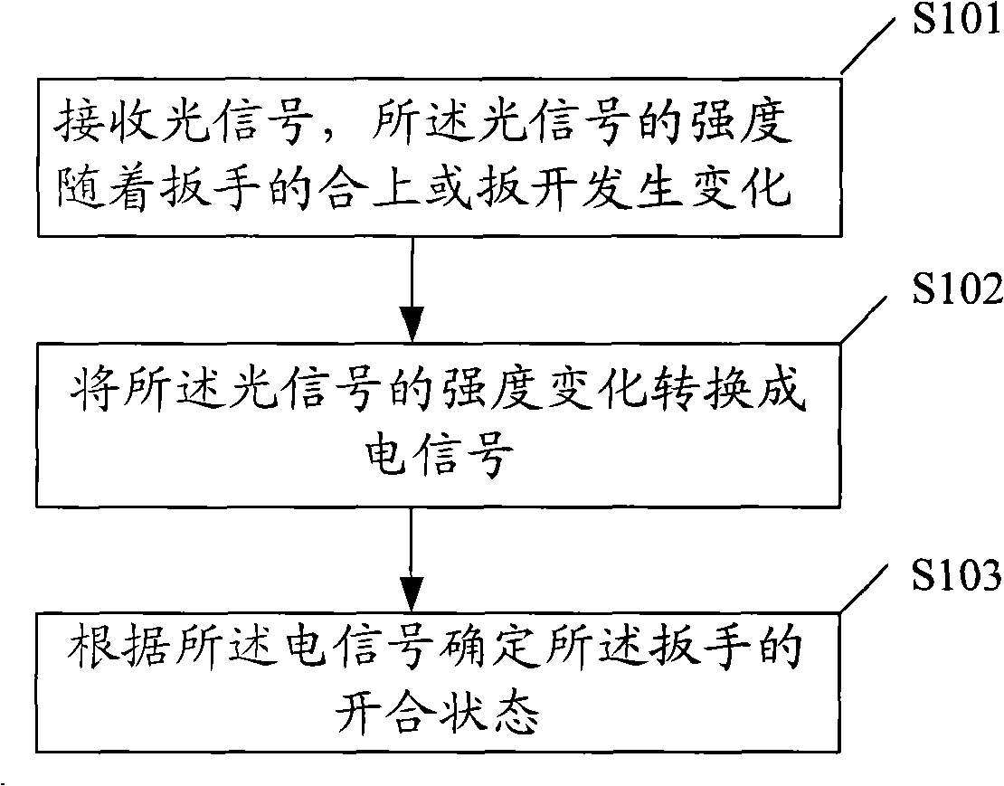
[0023] figure 1 A schematic flow chart of a method for detecting the opening and closing state of a wrench provided in an embodiment of the present invention, including:

[0024] Step S101, receiving an optical signal, the intensity of which changes as the wrench is closed or opened;

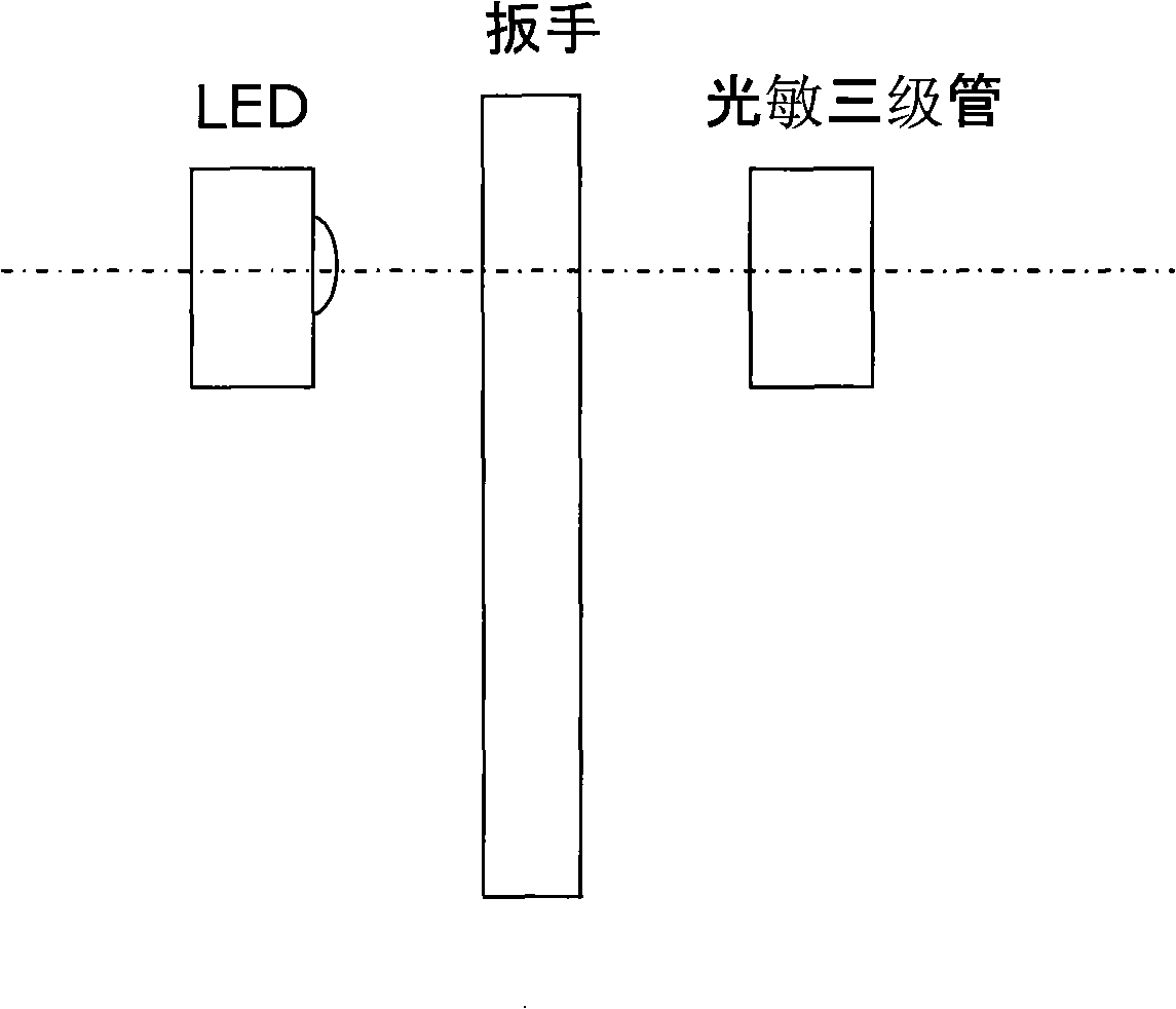
[0025] When the wrench is switched between closed and opened states, the light signal emitted by the light source can be blocked when the wrench is closed or opened, so that the intensity of the light signal changes, so that the change of the light signal can reflect the wrench The open or closed state (also known as the open and close state). In one embodiment, the position of the light source can be adjusted so that when the wrench is closed, all or part of the optical signal is blocked, so that the received optical signal is the weakest, and when the wrench is opened, all optical signals are not blocked by the wrench Or only a small part is blocked, so that the received light signal is the ...

Embodiment 2

[0034] This embodiment introduces an application scenario of the above method for detecting the opening and closing state of a wrench.

[0035] General communication equipment needs to use the handle bar, which is used to insert the veneer fixed on the handle bar into the frame in the chassis by pushing and pulling. hold. Normally, when the board is plugged into the communication equipment, the wrench is closed; when the board needs to be pulled out, the wrench should be opened in advance, and finally the handle bar and the board are pulled out with the help of the wrench . Before the board is pulled out from the device, it is necessary to predict that the device system board will be pulled out in advance, so that the system can perform preprocessing before the removal to ensure the normal operation of the device. By adopting the method for detecting the opening and closing state of the wrench provided in the embodiment of the present invention, it can be judged according to...

Embodiment 3

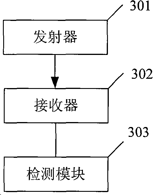
[0037] image 3 It is a schematic structural diagram of a device for detecting the opening and closing state of a wrench provided by an embodiment of the present invention. The device includes:

[0038] The transmitter 301 is used to generate an optical signal; specifically, the transmitter may be a light emitting diode (LED), a laser diode, or an infrared emitting diode, and the like.

[0039] The receiver 302 is configured to receive the optical signal generated by the generating unit, and convert the optical signal into an electrical signal; when the wrench is opened or closed, the intensity of the optical signal received by the receiver changes. Specifically, the receiver may be a photodiode or a phototransistor.

[0040] The detection module 303 is configured to detect the opening and closing state of the wrench according to the electrical signal. Specifically, it can be judged whether the wrench is in the opened or closed state according to the change or presence or ab...


PUM


Abstract

The embodiment of the invention discloses a method for detecting the open-close state of a spanner. The method comprises the following steps: receiving an optical signal, the intensity of which is changed along with the closing or the opening of the spanner; converting the intensity change of the optical signal into an electrical signal; and determining the open-close state of the spanner according to the electrical signal. In the embodiment, the change of the optical signal generated by the covering of the optical signal emitted from a light source when the spanner is opened or closed is utilized, then the change of the optical signal is converted into the electrical signal, and thereby the open-close state (open or closed) of the spanner can be detected by utilizing the electrical signal. During the entire open-close state detection process, no mechanical problem is involved, the requirement on mechanical treatment is low, and the reliability is enhanced. The embodiment also discloses a device for detecting the open-close state of the spanner.

Description

technical field [0001] The invention relates to the field of communication technology, in particular to a method and device for detecting the opening and closing state of a wrench. Background technique [0002] Due to its high reliability and the existence of backup equipment, all communication devices require that the functional boards in the subrack be automatically sensed in advance before being pulled out, and the relevant processing modules in the communication devices do the processing before the boards are pulled out. Processing, to ensure the normal operation of the business or function of the communication equipment. [0003] At present, the single board on most communication devices will place a switch on the handle bar of the front panel, and the mechanical force of closing or opening the handle bar will trigger the switch to open or close, thereby notifying the relevant processing module through the electrical characteristics of the switch Whether there is a dem...

Claims


Application Information

Patent Timeline
IPC IPC(8): G01V8/12H04L12/56
Inventor 黄春明
Owner HUAWEI TECH CO LTD
Why Eureka
Try Eureka