Radiating plate, interspace adjustable cooling clamper and mainboard
A technology of heat dissipation plate and spacing, applied in instruments, electrical digital data processing, digital data processing parts and other directions, can solve the problems of affecting the operation of electronic parts and high temperature, and achieve the effect of improving the heat dissipation effect and increasing the heat dissipation area.
- Summary
- Abstract
- Description
- Claims
- Application Information
AI Technical Summary
Problems solved by technology
Method used
Image

Examples
no. 1 example
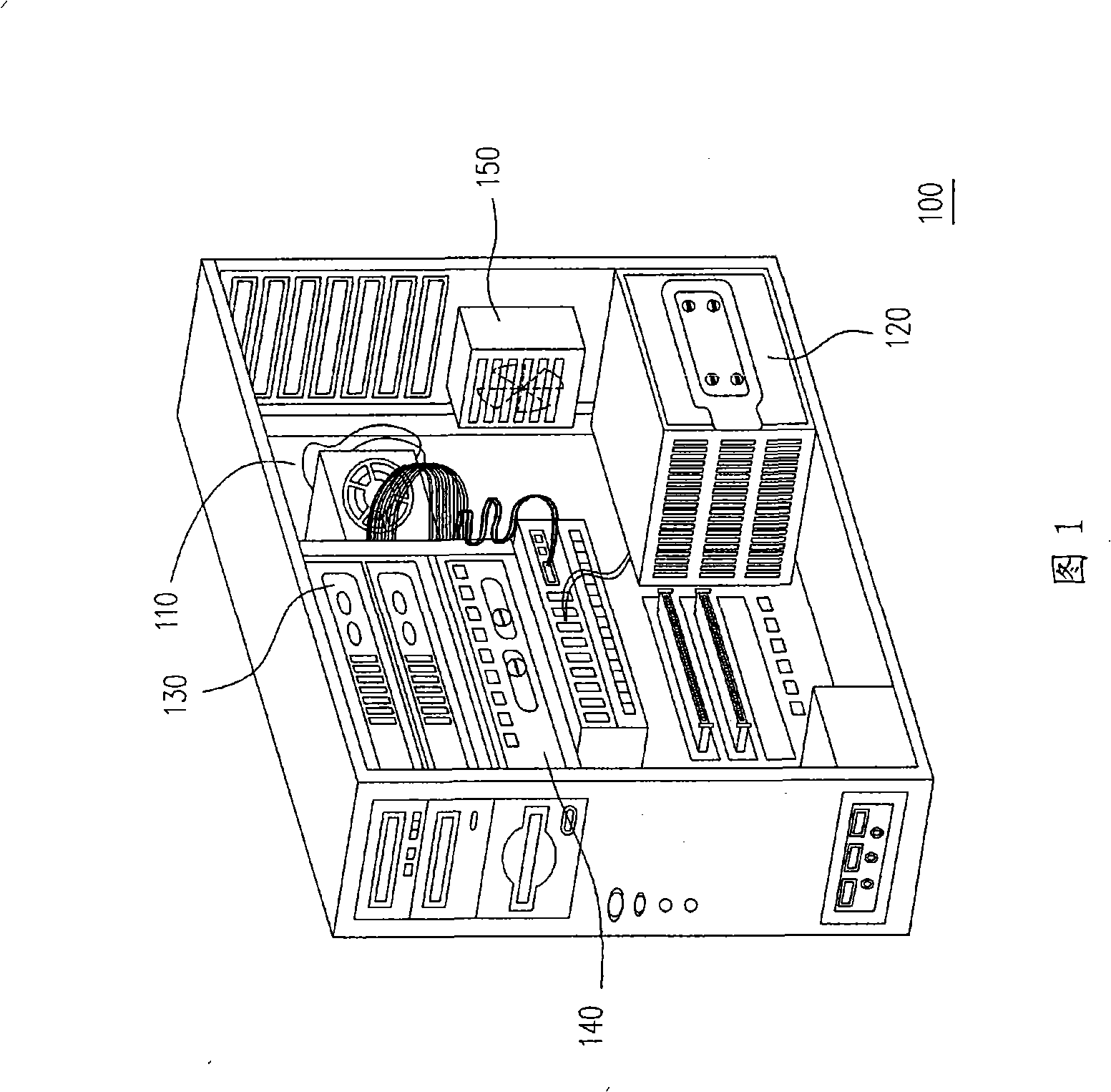
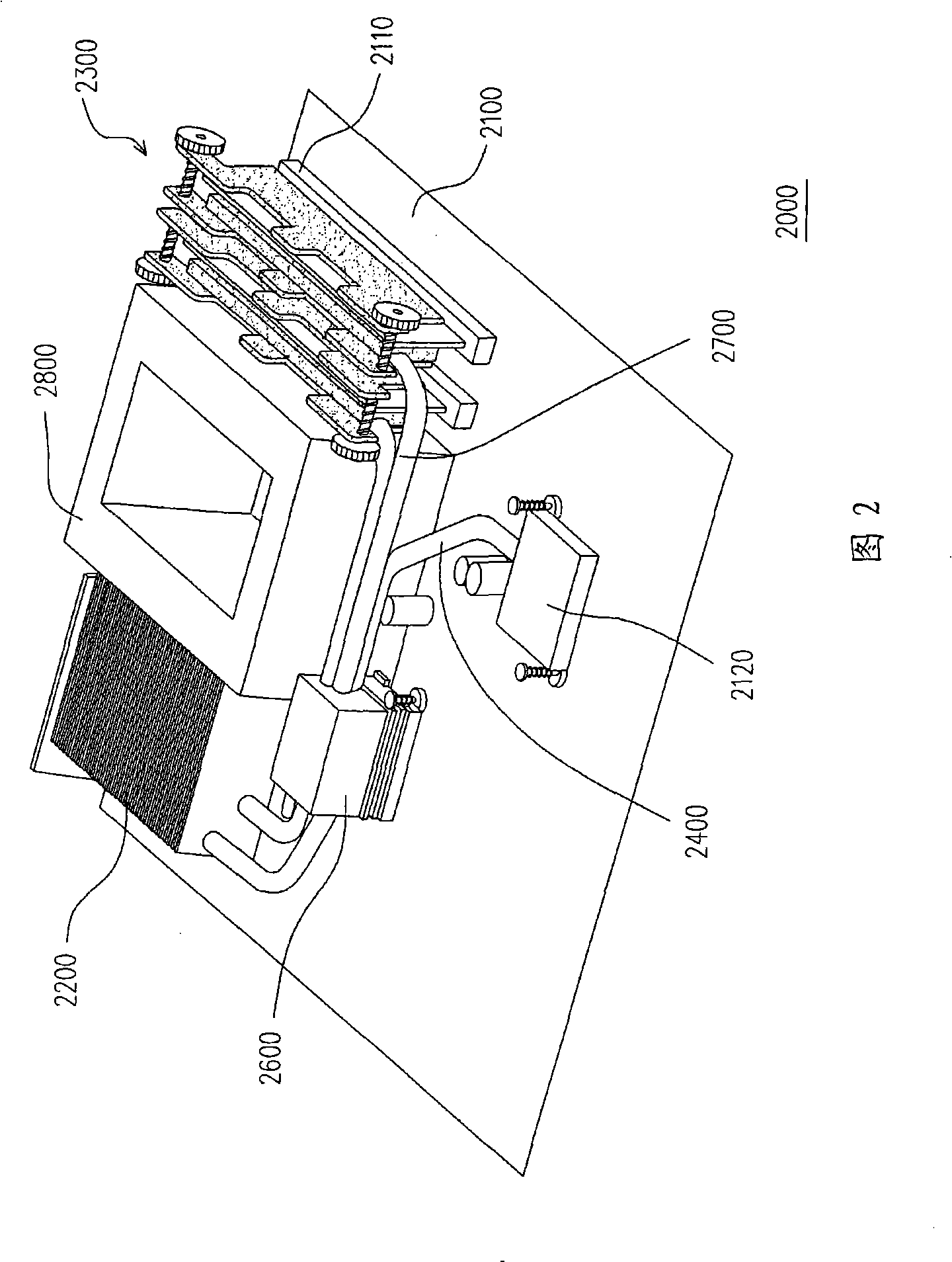
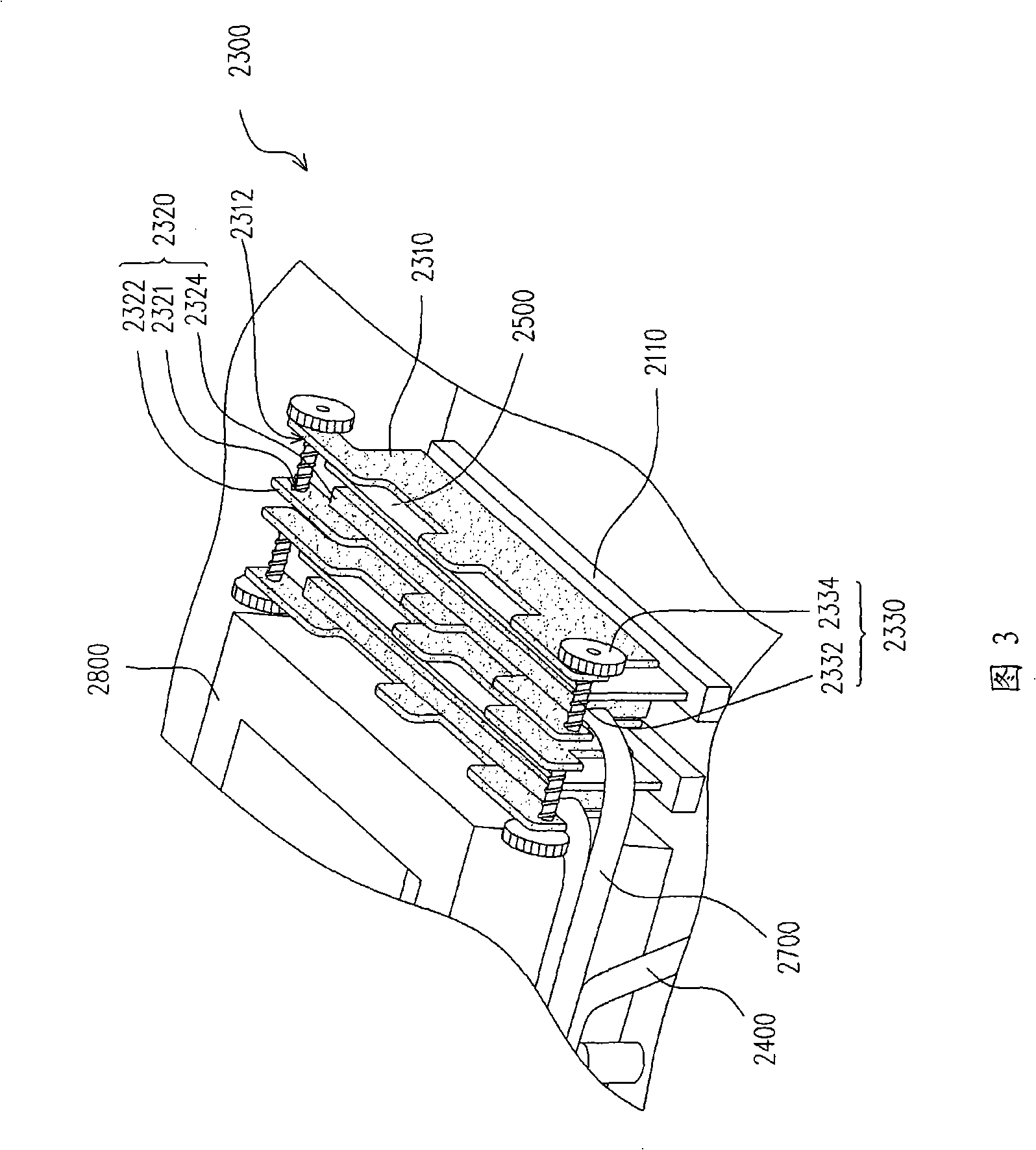
[0050] FIG. 2 is a schematic diagram of the main board according to the first embodiment of the present invention, and FIG. 3 is a schematic diagram of the heat dissipation fixture with adjustable pitch in FIG. 2 . Please refer to FIG. 2 and FIG. 3 at the same time. The motherboard 2000 includes a substrate 2100 , a heat sink 2200 and a heat dissipation fixture 2300 with adjustable spacing.
[0051] The substrate 2100 has at least one socket 2110 and at least one first heat source. The first heat source is, for example, the south bridge chip 2120, which is responsible for controlling the peripheral devices connected to the peripheral component interface (PCI) bus. In addition, there is a north bridge chip (not shown) on the substrate 2100, and the north bridge chip is responsible for processing the signal transmission between the central processing unit (CPU), the main memory (Main Memory) and the peripheral component interface (Peripheral Component Interface, PCI) bus. The s...
no. 2 example
[0067] This embodiment is substantially the same as the first embodiment, and the same or similar component numbers represent the same or similar components. FIG. 6 is a schematic diagram of a heat sink placed on a motherboard according to a second embodiment of the present invention. Please refer to FIG. 2 and FIG. 6 at the same time. The cooling plate 200 is placed on the memory card slot (not shown) to contact the memory chip 2520 of the memory card 2500 on the motherboard 2000 to assist the memory card 2500 in cooling.
[0068] The cooling plate 200 includes a body 210 , a holding seat 220 and a heat pipe 230 . The body 210 has a surface facing the memory chip 2520 . The holding seat 220 is disposed on the surface and is suitable for contacting the memory chip 2520 . The body 210 and the holding seat 220 can be integrally formed, and the material of the body 210 and the holding seat 220 is a good conductor of heat, such as metal. One end of the heat pipe 230 is embedded...
PUM
 Abstract
Description
Claims
Application Information
 - Generate Ideas
- Intellectual Property
- Life Sciences
- Materials
- Tech Scout
- Unparalleled Data Quality
- Higher Quality Content
- 60% Fewer Hallucinations
Browse by: Latest US Patents, China's latest patents, Technical Efficacy Thesaurus, Application Domain, Technology Topic, Popular Technical Reports.
© 2025 PatSnap. All rights reserved.Legal|Privacy policy|Modern Slavery Act Transparency Statement|Sitemap|About US| Contact US: help@patsnap.com