Changeable one-shot forming edge-neatening rose reamer and process for manufacturing the same

A manufacturing process and replaceable technology, applied in the direction of manufacturing tools, accessories of tool holders, metal processing equipment, etc., can solve the problems of overall damage and scrapping, low product quality, easy damage of tools, etc., to achieve easy processing and manufacturing, and products The effect of high precision and easy replacement

Inactive Publication Date: 2008-12-17
王建波
View PDF2 Cites 19 Cited by
  • Summary
  • Abstract
  • Description
  • Claims
  • Application Information

AI Technical Summary

Problems solved by technology

The structure of the above-mentioned improvement plan is complicated, the quality of the produced product is no

Method used


Image

  • Changeable one-shot forming edge-neatening rose reamer and process for manufacturing the same
  • Changeable one-shot forming edge-neatening rose reamer and process for manufacturing the same
  • Changeable one-shot forming edge-neatening rose reamer and process for manufacturing the same

Examples


Embodiment 1

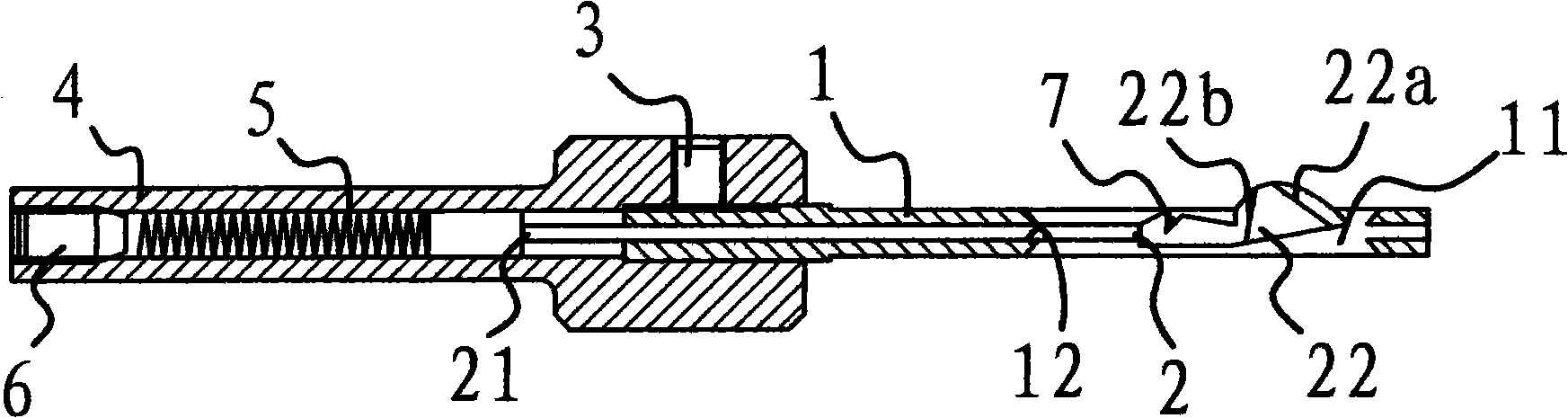
[0027] Such as figure 1 As shown, the replaceable one-time molding trimming and chamfering cutter includes a mandrel 1 and a cutter 2 installed on the mandrel 1 . The tool 2 has a strip-shaped cutter bar 21 and a cutter head 22 located at one end of the cutter bar 21. The cutter head 22 has a front cutting edge 22a and a rear cutting edge 22b, and an elastic closed groove is opened on the mandrel 1. 11. The cutter head 22 is set in the elastic closed groove 11, and an adjustment mechanism is provided between the mandrel 1 and the cutter bar 21 of the cutter 2.

[0028] In this embodiment, the mandrel 1 is provided with a central hole 12 connected with the elastic closed groove 11, the tool bar 21 is inserted in the central hole 12, and its end passes through the central hole 12, and the mandrel 1 is fixed on the On the adapter 4 , the above-mentioned adjusting mechanism includes a spring 5 and an adjusting screw 6 installed on the adapter 4 , one end of the spring 5 acts on t...

Embodiment 2

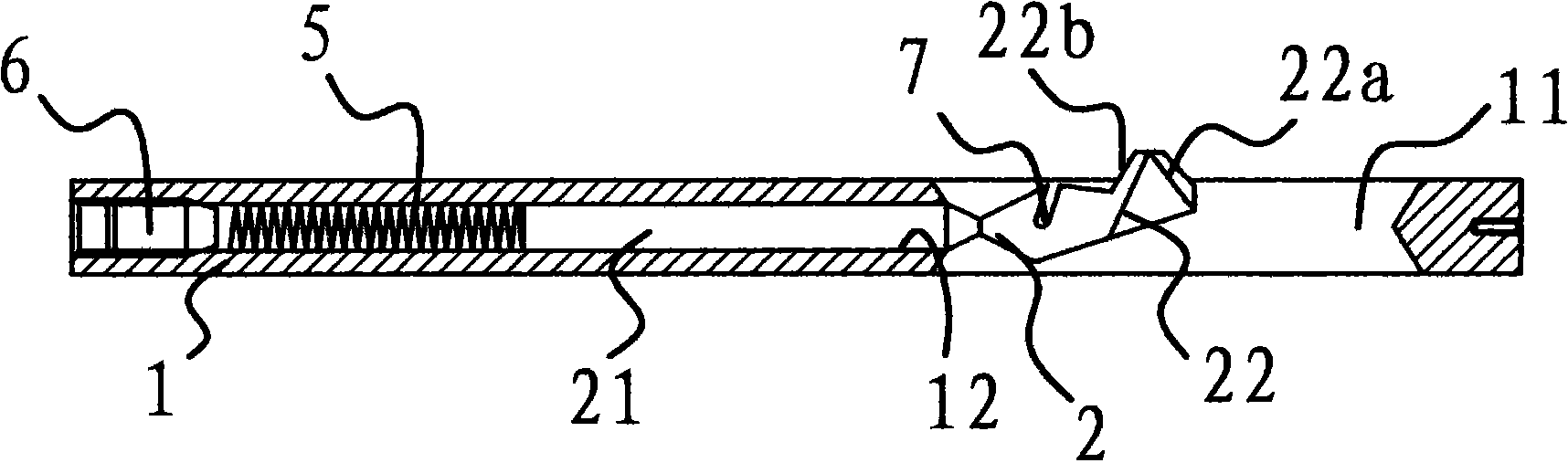
[0044] Such as figure 2 As shown, in this embodiment, the mandrel 1 is provided with a central hole 12 connected with the elastic closed groove 11, and the knife rod 21 is inserted in the central hole 12. The above-mentioned adjustment mechanism includes a spring 5 and a spring installed in the central hole. 12 of the adjusting screw 6, one end of the spring 5 acts on the knife bar 21, and the other end acts on the adjusting screw 6. The rest are similar to those in Example 1, and will not be described in detail herein.

Embodiment 3

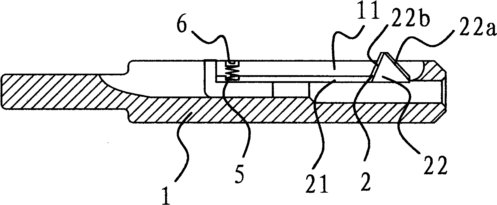
[0046] Such as image 3 As shown, in this embodiment, the adjustment mechanism is arranged on the adjustment screw 6 and the spring 5 on the side of the mandrel 1 , one end of the spring 5 acts on the knife rod 21 , and the other end acts on the adjustment screw 6 . The rest are similar to those in Example 1, and will not be described in detail herein.


PUM

PropertyMeasurementUnit
Hardnessaaaaaaaaaa

Abstract

The invention relates to a changeable and once-forming trimming chamfer cutter and a manufacturing process thereof, being particularly suitable for double-sided chamfering and deburring of through holes, composite holes and half through holes of various composite complex bodies. The device comprises a core shaft and a cutting tool which is arranged on the core shaft. The device is characterized in that the cutting tool is provided with a strip-shaped arbor and a knife head which is at one end of the arbor, the knife head is provided with a front cutting edge and a back cutting edge, the core shaft is opened with an elastic closed slot, the knife head is arranged in the elastic closed slot and a governing mechanism is arranged between the core shaft and the arbor of the cutting tool. Compared with the prior art, the invention has the following advantages: 1. the chamfer cutter has reasonable design and simple structure, and the cutting tool can be changed conveniently without any damage to work pieces, and the processed products have high precision. 2. chamfering and deburring of the two ends of the hole can be completed once with wide application range. 3. the chamfer cutter has simple processing technology, easy processing and manufacture and convenient assembly and disassembly.

Description

technical field [0001] The invention relates to the field of mechanical technology, in particular to a replaceable once-formed edge trimming and chamfering knife, which is especially suitable for double-sided chamfering and deburring of through holes, combined holes and half through holes of various combined complex bodies. Background technique [0002] In the processing of modern mechanical parts, parts, assemblies, and complex bodies that require through-hole processing are often chamfered by boring machines. However, the apertures are generally relatively large; lathes can also use longer tool bars to process some chamfers that can be used to clamp rotating parts, but these methods are difficult to achieve one-time molding, trimming, and chamfering of various apertures in the component body. horn. With the development of mechanical manufacturing technology, engineers and technicians are required to solve various mechanical manufacturing problems, and new requirements are...

Claims


Application Information

Patent Timeline
IPC IPC(8): B23B27/06B23P15/28
Inventor 王建波
Owner 王建波
Why Eureka
Try Eureka