

Flow guide and ultraviolet disinfecting reactor
A technology of ultraviolet disinfection and deflector, applied in the direction of light water/sewage treatment, irradiation, etc., can solve the problems that the sterilization efficiency needs to be further improved, and achieve the effects of easy implementation and promotion, increased killing quantity, and simple structure
Inactive Publication Date: 2010-12-01
SICHUAN UNIV
View PDF0 Cites 0 Cited by
- Summary
- Abstract
- Description
- Claims
- Application Information
AI Technical Summary
Problems solved by technology
Although this kind of reactor has a simple structure, its bactericidal efficiency needs to be further improved.
Method used
View moreImage
Smart ImageViewing Examples

Examples
Embodiment 1
Embodiment 2
Login to View More PUM
 Abstract
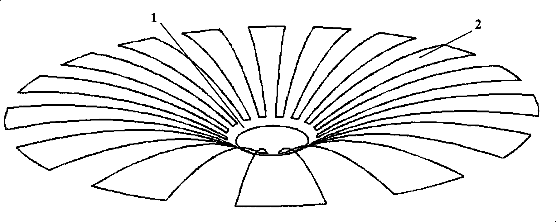
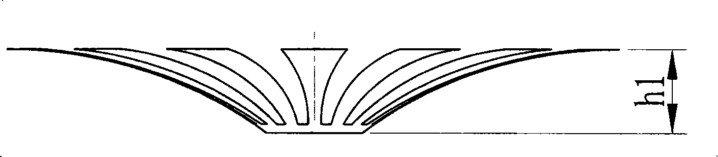
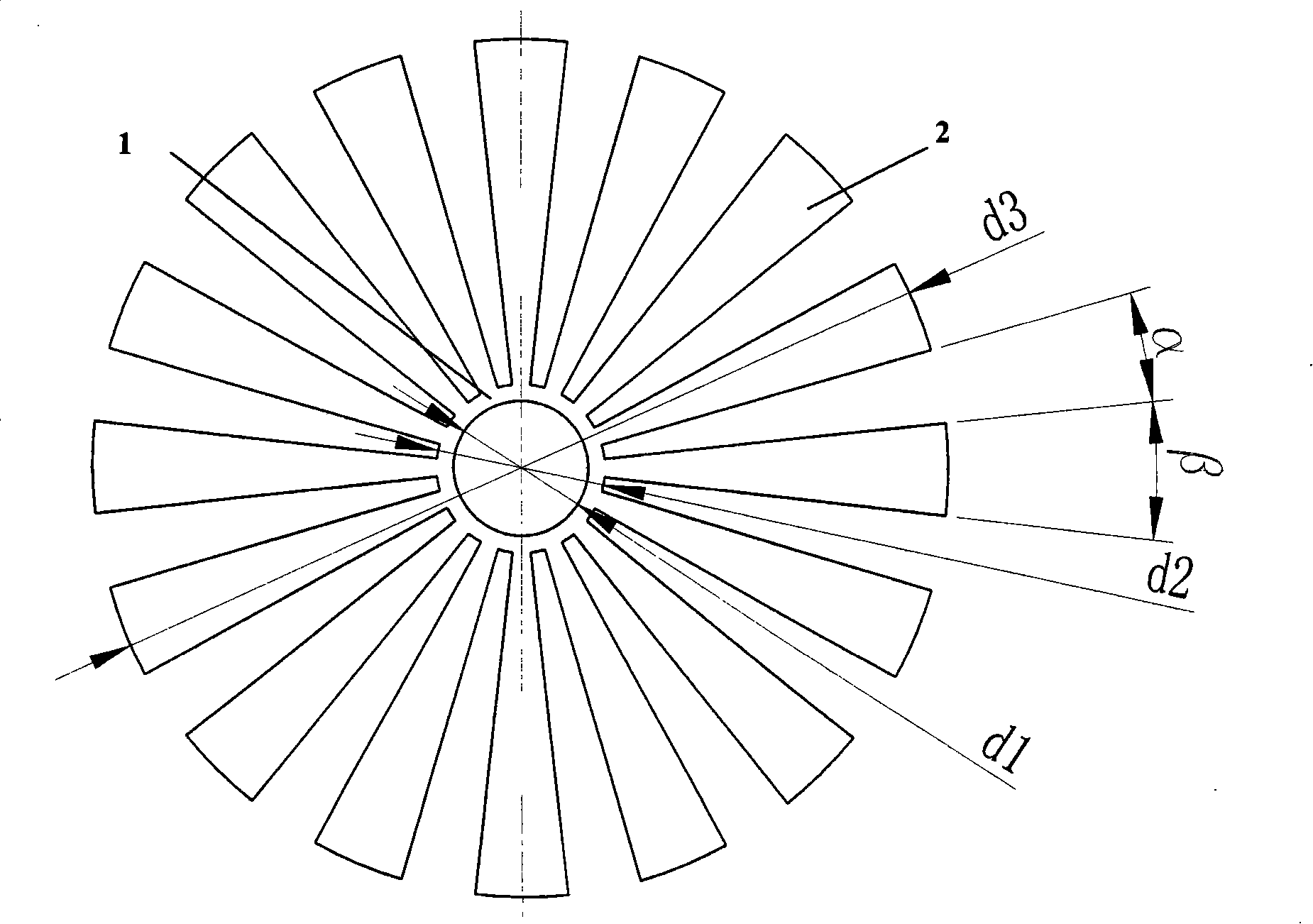
A fluid director comprises an upward-bended arc-ring and at least eight arc discs provided with the radius which is the identical to the axial-bended radius of the arc-ring, and a horizontal projection of each arc disc is a part of the ring, and the central angle is Beta, and the arc discs are equally distributed along the edge of the arc-ring at an interval of the central angle Alpha and are integrated with the arc-ring, wherein, Alpha is less than Beta. An ultraviolet disinfection reactor of the invention comprises a casing, a cover, an ultraviolet light tube, a light tube limiting spring and the fluid director with the above form. A water inlet is cut at the bottom of the casing, and a water outlet is cut on the side wall of the casing; the fluid director is arranged on the lower part of the ultraviolet light tube and on the upper part of the water inlet cut at the bottom of the casing. As the fluid director can change the flowing state of fluid and can increase the flowing time offluid through a certain of path, then the fluid director is arranged in the ultraviolet disinfection reactor to prolong the retaining time of germ in a disinfection cavity so as to enhance the killing rate of germ or to enhance the water quantity to be disinfected with the same germ killing rate.
Description
Flow deflector and UV disinfection reactor technical field The invention relates to a diversion device and an ultraviolet radiation disinfection device for changing the flow state of water flow, in particular to an ultraviolet disinfection reactor and a diverter used in conjunction with it to enhance the killing efficiency of germs. Background technique Ultraviolet disinfection is a method of disinfection of drinking water. When bacteria in drinking water are irradiated by ultraviolet rays, the energy of the ultraviolet spectrum is absorbed by the DNA of the bacteria. When the radiation reaches a certain amount, the DNA structure of the bacteria is damaged, thereby To achieve the purpose of killing germs. It is understood that the existing ultraviolet disinfection reactor for drinking water disinfection includes a shell, a shell cover installed on the upper end of the shell, an ultraviolet lamp installed on the shell cover and located in the shell, and a lamp limiter fixe...
Claims
Login to View More Application Information
Patent Timeline
 Patent Type & AuthorityPatents(China)
IPC IPC(8): A61L2/10C02F1/32
Inventor周晓泉刘琳莉
OwnerSICHUAN UNIV