
Machine-tooled method for cylinder jacket inner bore surface and fine boring squeezing knife tool

A surface machining and surface processing technology, which is applied in the direction of lathe cutting tools, manufacturing tools, metal processing equipment, etc., can solve the problems of improving the metal tightness of the inner wall of the cylinder liner, loose metal on the surface of the inner hole of the cylinder liner, and the metal of the cylinder liner. Loose tightness and other problems, to achieve the effect of improved tightness, improved wear resistance, and extended service life

Active Publication Date: 2008-12-24
洛阳百成内燃机配件有限公司
View PDF0 Cites 8 Cited by
  • Summary
  • Abstract
  • Description
  • Claims
  • Application Information

AI Technical Summary

Problems solved by technology

[0002] At present, the casting technology of internal combustion engine cylinder liners mostly adopts centrifugal casting, which will inevitably lead to looser metal tightness of the inner wall of the inner hole surface of the cylinder liner than that of the outer wall; the fine boring process of the inner hole surface (inner wall) of the cylinder liner after casting is only for The removal of the machining allowance cannot improve the metal tightness of the inner wall of the cylinder liner; due to the loose metal on the surface of the inner hole of the cylinder liner, the surface (inner wall) of the inner hole of the cylinder liner is easy to wear and prematurely wear during the use of the engine. scrapped

Method used


Image

  • Machine-tooled method for cylinder jacket inner bore surface and fine boring squeezing knife tool
  • Machine-tooled method for cylinder jacket inner bore surface and fine boring squeezing knife tool
  • Machine-tooled method for cylinder jacket inner bore surface and fine boring squeezing knife tool

Examples


Embodiment Construction

[0015] Provide embodiment of the present invention in conjunction with accompanying drawing:

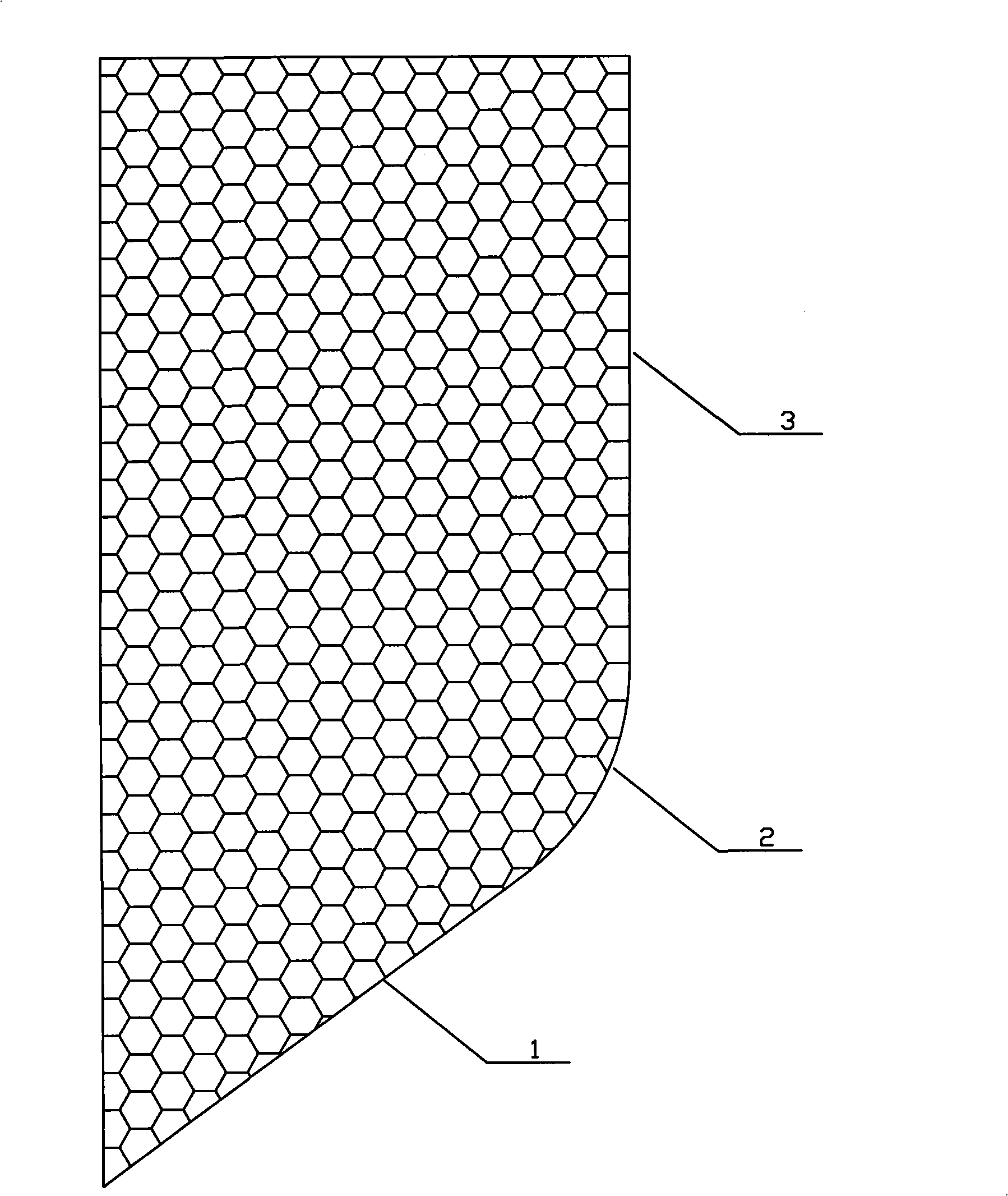
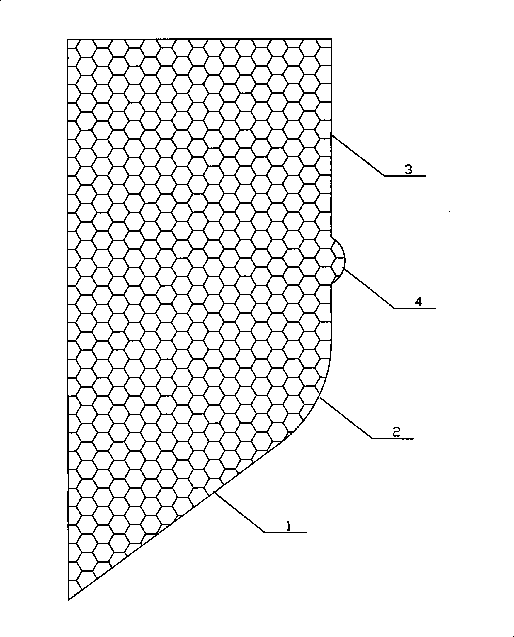
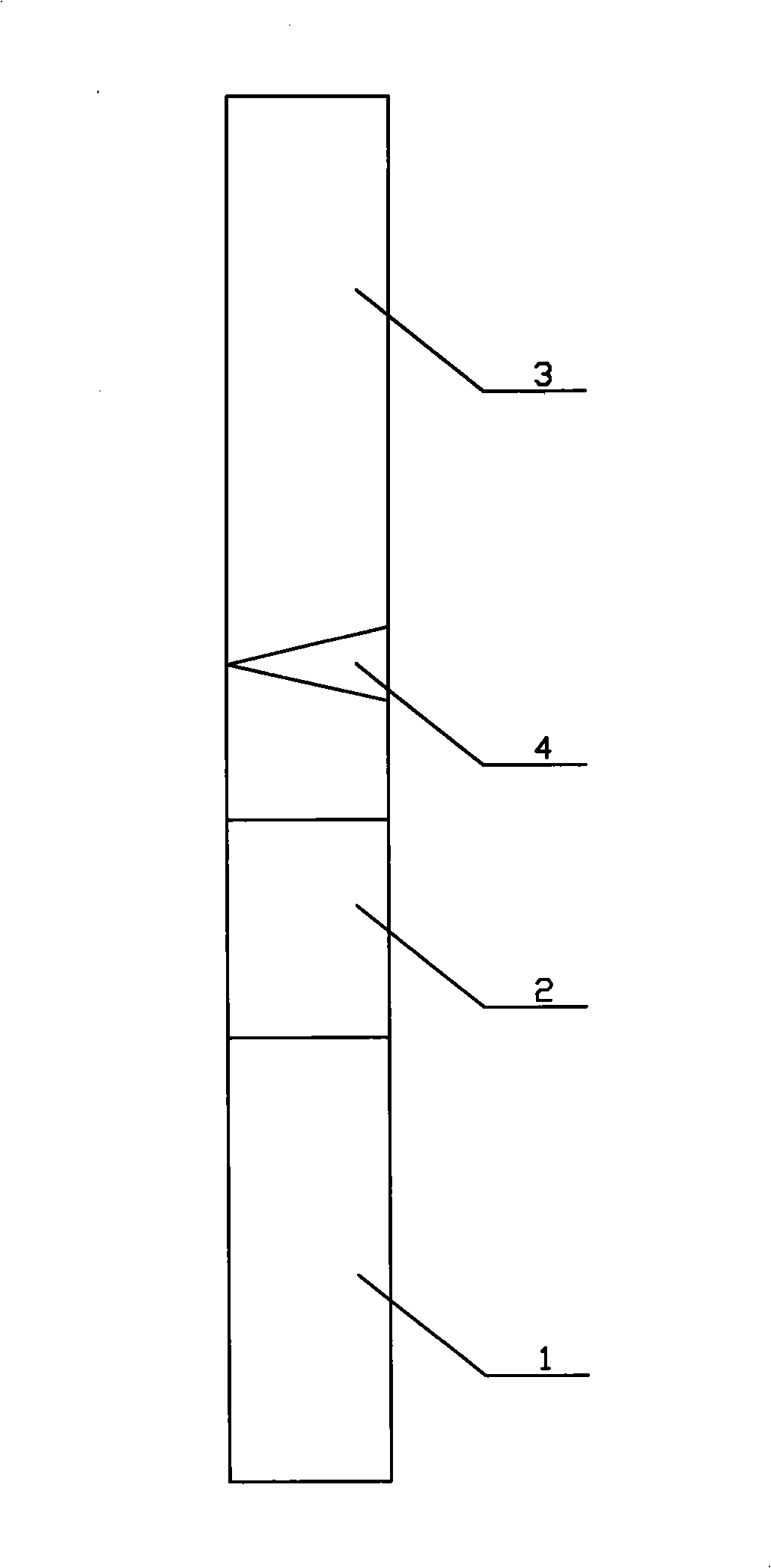
[0016] Such as figure 2 , image 3 As shown, the lower slope of the proposed fine boring extrusion tool has the main cutting edge 1, the right straight surface is the wiper edge 3, the arc transition surface between the main cutting edge and the wiper edge is the auxiliary cutting edge 2, and the wiper edge 3 has an extruding cone 4, and the arc of the extruding cone 4 increases gradually along the direction of tool rotation. The extruding cone 4 is a cone obtained by beveling from the top of the cone to the bottom of the cone. The arc is 25-35 degrees; the arc body of the extrusion cone 4 gradually increases along the direction of tool rotation, which can prevent the extrusion cone from cutting the inner wall of the cylinder liner and ensure that the extrusion cone 4 gradually pressurizes the inner wall of the cylinder liner Extruding, the extruding cone 4 can be located at the l...


PUM


Abstract

The invention belongs to the technical field of metal surface mechanical machining. The invention provides a mechanical machining method of the surface of an internal hole of a gas cylinder sleeve, which includes the following steps: a main cutting blade (1) and an auxiliary cutting blade (2) of a cutter are used to perform the major and the remaining cutting tasks; an extruding cone (4) of a smoothing blade (3) is used to extrude the surface of the internal hole of the gas cylinder sleeve after the cutting step, wherein, the smoothing blade (3) levels off the burrs formed in the process and smoothes the protuberances produced in the extrusion of the internal holes of the gas cylinder sleeve by the extruding cone (4). The precision boring cutter smoothing blade (3) is provided with the extruding cone (4), the arc of which increases gradually in the arc direction along the cutter, wherein, the extruding cone (4) has a conical body which is processed through cutting in the oblique direction from the top to the bottom of the conical body; the arc of the cone bottom is 25 to 35 degrees. The processing of the method improves the compactedness of the metal at the surface of the internal hole of the gas cylinder sleeve, thus improving the wear resistant performance of the internal wall of the gas cylinder sleeve and lengthening the service life of the engine.

Description

technical field [0001] The invention belongs to the metal surface mechanical processing technology, and mainly relates to a machining method for extruding the surface of the inner hole of the cylinder liner while finely boring the surface of the inner hole of the cylinder liner, and a fine boring extrusion tool. Background technique [0002] At present, the casting technology of internal combustion engine cylinder liners mostly adopts centrifugal casting, which will inevitably lead to looser metal tightness of the inner wall of the inner hole surface of the cylinder liner than that of the outer wall; the fine boring process of the inner hole surface (inner wall) of the cylinder liner after casting is only for The removal of the machining allowance cannot improve the metal tightness of the inner wall of the cylinder liner; due to the loose metal on the surface of the inner hole of the cylinder liner, the surface (inner wall) of the inner hole of the cylinder liner is easy to w...

Claims


Application Information

Patent Timeline
Patent Type & Authority Applications(China)
IPC IPC(8): B23B41/12B23P9/02B23B27/00
Inventor 田志超
Owner 洛阳百成内燃机配件有限公司
Learn More