Method for producing G group plate mode steel plate by the combination of digital control torch cutter and shears

A shearing machine, fire cutting machine technology, applied in shearing device, shearing machine equipment, gas flame welding equipment and other directions, can solve the problems of high production efficiency and low cutting efficiency, and achieve flexible and sufficient arrangement, which is beneficial to thick plates. The effect of yield and contract fulfillment capacity

Inactive Publication Date: 2008-12-24
BAOSHAN IRON & STEEL CO LTD
View PDF0 Cites 19 Cited by
  • Summary
  • Abstract
  • Description
  • Claims
  • Application Information

AI Technical Summary

Problems solved by technology

Among them, the steel plates of Group A and Group S modes can be produced by online cutting head shears, double-sided shears, split shears, and cut-to-length shears, and the production efficiency is high; the steel plates of Group G mode (that is, the scheduled flame gas cutting production mode) The steel plate can only be rolled off the production line by driving to the CNC fire cutting table for CNC fire cutting production, and the cutting efficiency is very low

Method used


Image

  • Method for producing G group plate mode steel plate by the combination of digital control torch cutter and shears
  • Method for producing G group plate mode steel plate by the combination of digital control torch cutter and shears

Examples


Embodiment 1

[0029] Take the shearing line of Baosteel Heavy Plate Plant as an example:

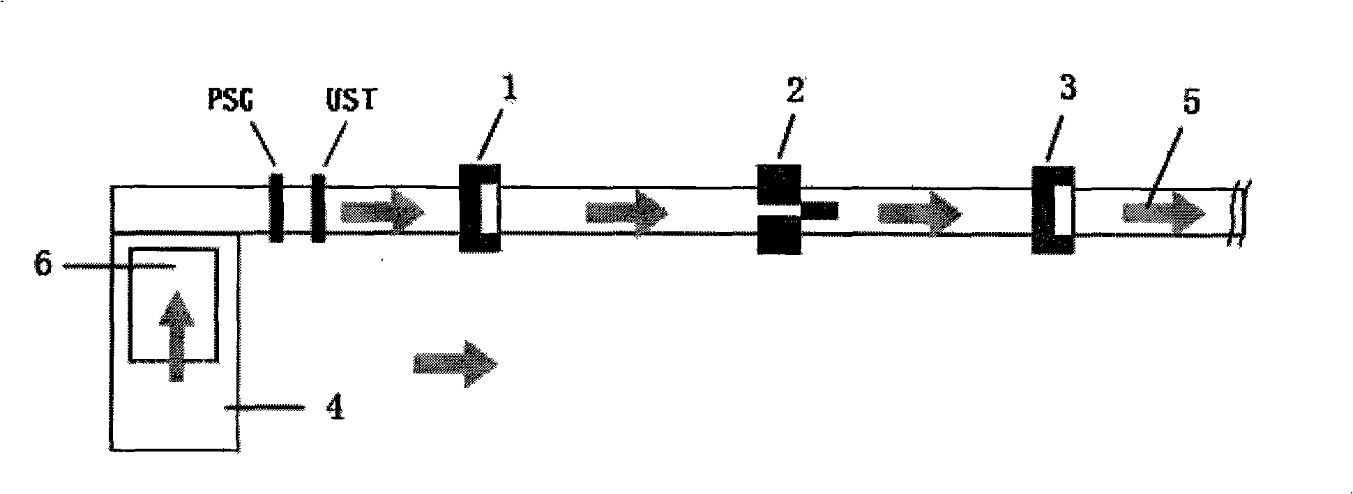
[0030] The production process and time-consuming situation of the original G group plate mode steel plate is: G group plate rolled large plate 6 is hoisted into the surface of the CNC cutting machine by a crane, it takes 5 minutes; the CNC cutting machine scans the steel plate and automatically sets the material to determine the cutting path , it takes 10 minutes; the CNC cutting machine cuts according to the set cutting path, and it takes 2 hours; the finished steel plate is hoisted from the surface of the CNC cutting machine by a crane, and it takes 15 minutes. It usually takes 15 minutes to cut a G group plate mode steel plate. More than 2.5 hours.

[0031] see figure 1 It is a necessary condition for the realization of this technology that the thick plate shearing line and the CNC flame cutting machine are arranged within the same workshop span. Such equipment arrangement provides the possibility...

Embodiment 2

[0047] Except in this embodiment, the value of the splitting slit width is as follows:

[0048] Steel plate thickness (mm)

Slit width(mm)

0~10

1.00-1.10

10~20

1.50-1.60

20~40

2.60-2.70

40~50

3.50-3.60

[0049] Except that the shear margin is set at 8-10 mm, the others are the same as in Embodiment 1, and the method of combining the numerical control fire cutting machine and the shearing machine of the present invention to produce the G group plate model steel plate is carried out.

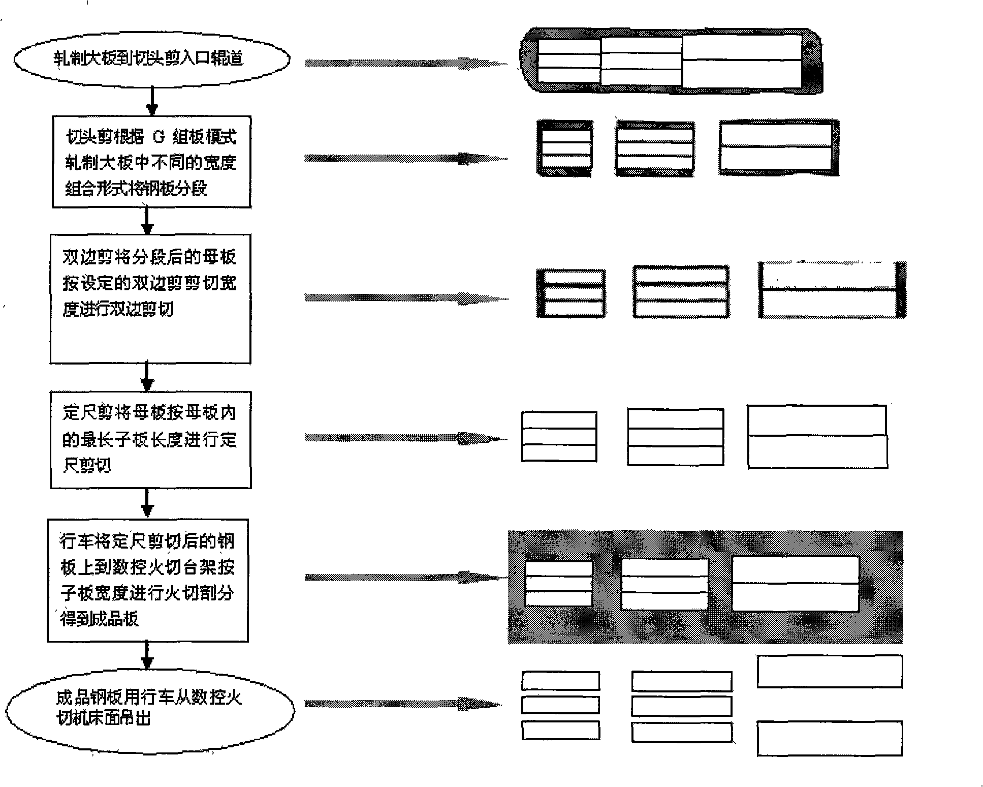
[0050] As mentioned above, according to the method of combining the numerical control fire cutting machine and the shearing machine in the above two embodiments to produce the G-group pattern steel plate, according to the original G-group pattern steel plate production process, it usually takes 2.5 hours to cut a G-group pattern steel plate in total. Above, and in the above-mentioned embodiment, the cutting process of t...


PUM


Abstract

The present invention discloses a production method which utilizes a numerically controlled flame cutter and a shearer to produce G-group plate mode steel plates. The method adopts the numerically controlled flame cutter and the shearer assembly (a pair of crop shears, a pair of double-side shears, a pair of slitting shears and a pair of cut-to-length shears) to produce G-group plate mode steel plates. The process includes steel plate segmentation, width cut-to-length shearing, length cut-to-length shearing and slitting. On the premise of ensuring the dimensional precision of the length and the width of a steel plate, the method effectively resolves the problem of low working efficiency in the production of G-group plate mode steel plates, the cutting period of a single G-group plate mode steel plate can be reduced by about one hour, and the total cutting time can be decreased by 40 percent. The method is adapted to the production of thick steel plates.

Description

technical field [0001] The present invention relates to a method for producing a patterned steel plate of a group, in particular, the invention relates to a method for producing a patterned steel plate of a G group by combining a numerical control fire cutter and a shearing machine. Background technique [0002] After the wide and thick steel plate production plant receives the steel plate contract in the market, the material design department will arrange different slabs for rolling production according to the number, length, width, thickness, steel type and other factors of the contract steel plate, that is, each slab will be rolled The large rolled slabs usually contain multiple contract slabs, and there are three main slab group modes: A group slab mode, S group slab mode, and G group slab mode. Among them, the steel plates of Group A and Group S modes can be produced by online cutting head shears, double-sided shears, split shears, and cut-to-length shears, and the prod...

Claims


Application Information

Patent Timeline
Patent Type & Authority Applications(China)
IPC IPC(8): B23P13/00B23P23/06B23D31/00B23K7/00
Inventor 李剑张向葵
Owner BAOSHAN IRON & STEEL CO LTD
Why Eureka
Try Eureka