Printing quality control method and system for relief printing press

A technology for printing quality and management methods, applied in gravure rotary printing machines, general parts of printing machinery, printing machines, etc., can solve the problems of quality fluctuation, cost increase, increase operator burden, etc. Avoid the effects of adjustment errors

Inactive Publication Date: 2008-12-24
KOMORI CORP
View PDF3 Cites 4 Cited by
  • Summary
  • Abstract
  • Description
  • Claims
  • Application Information

AI Technical Summary

Problems solved by technology

[0007] Therefore, in the past, the operator had to repeat printing many times, check the printed material, and adjust each clamping pressure and printing pressure. This not only increased the burden on the operator, but also because the operator made the adjustment intuitively, so Adjustment errors will cause quality fluctuations and produce a large number of damaged paper, resulting in increased costs

Method used


Image

  • Printing quality control method and system for relief printing press
  • Printing quality control method and system for relief printing press
  • Printing quality control method and system for relief printing press

Examples


Embodiment 1

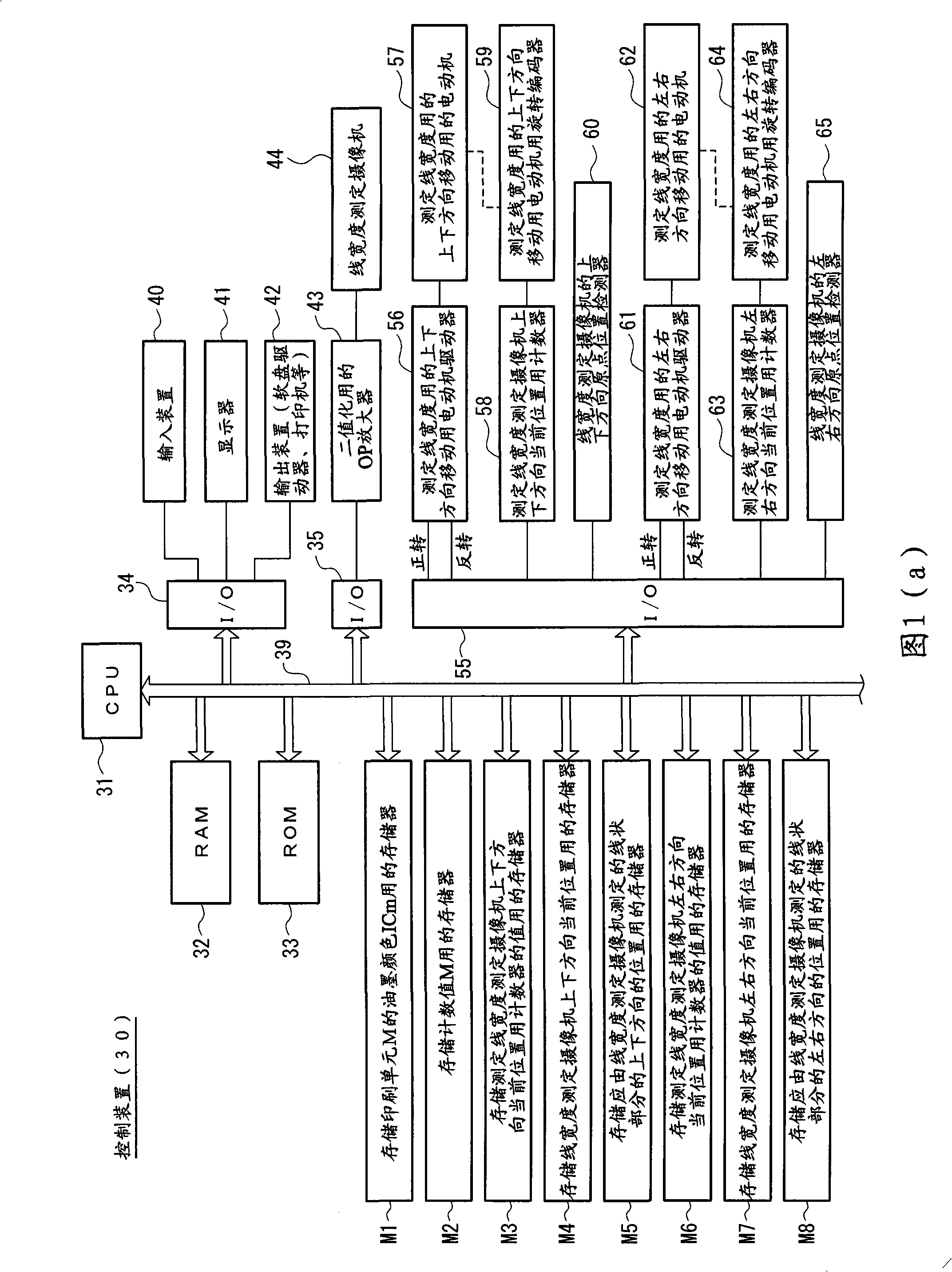
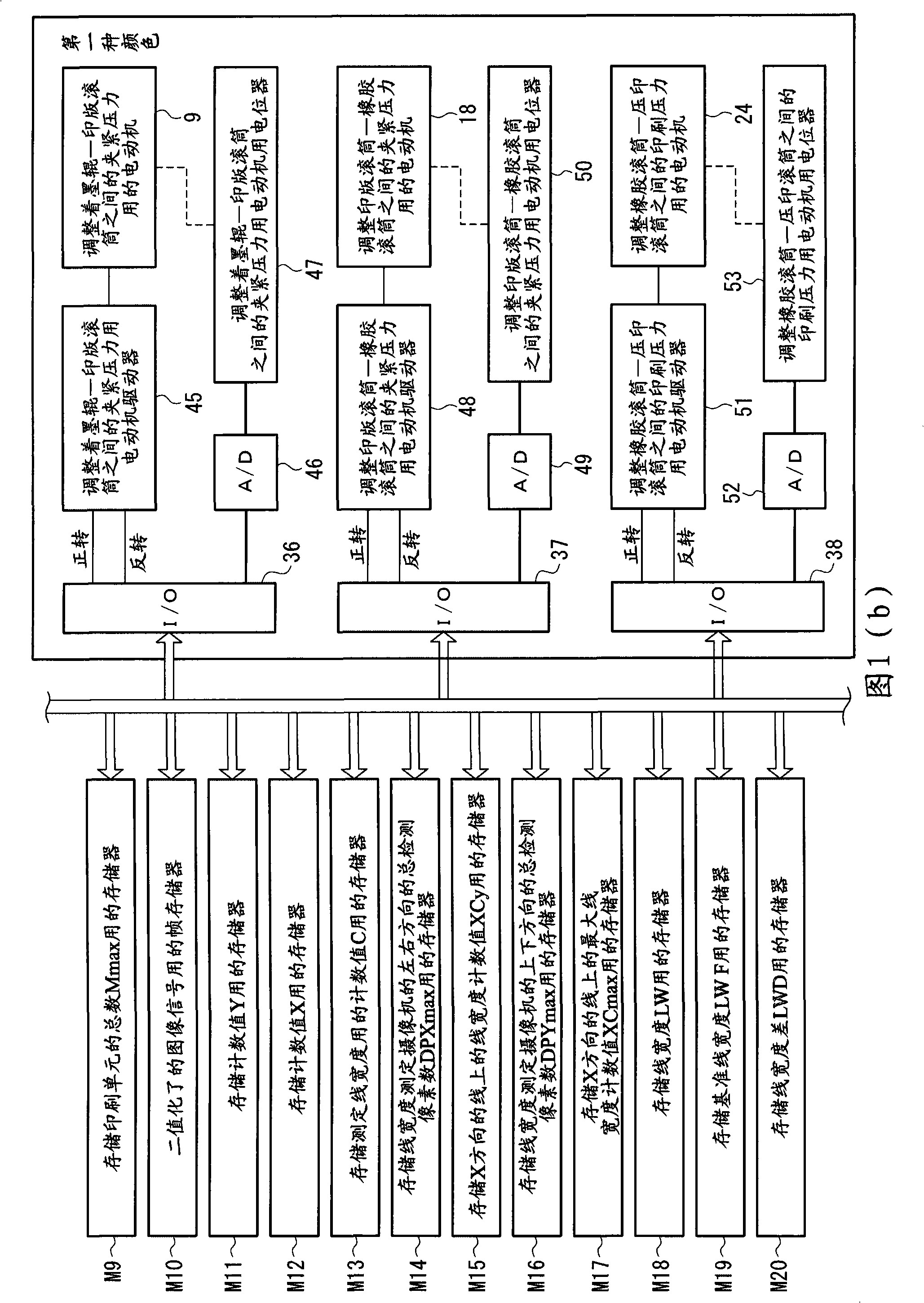
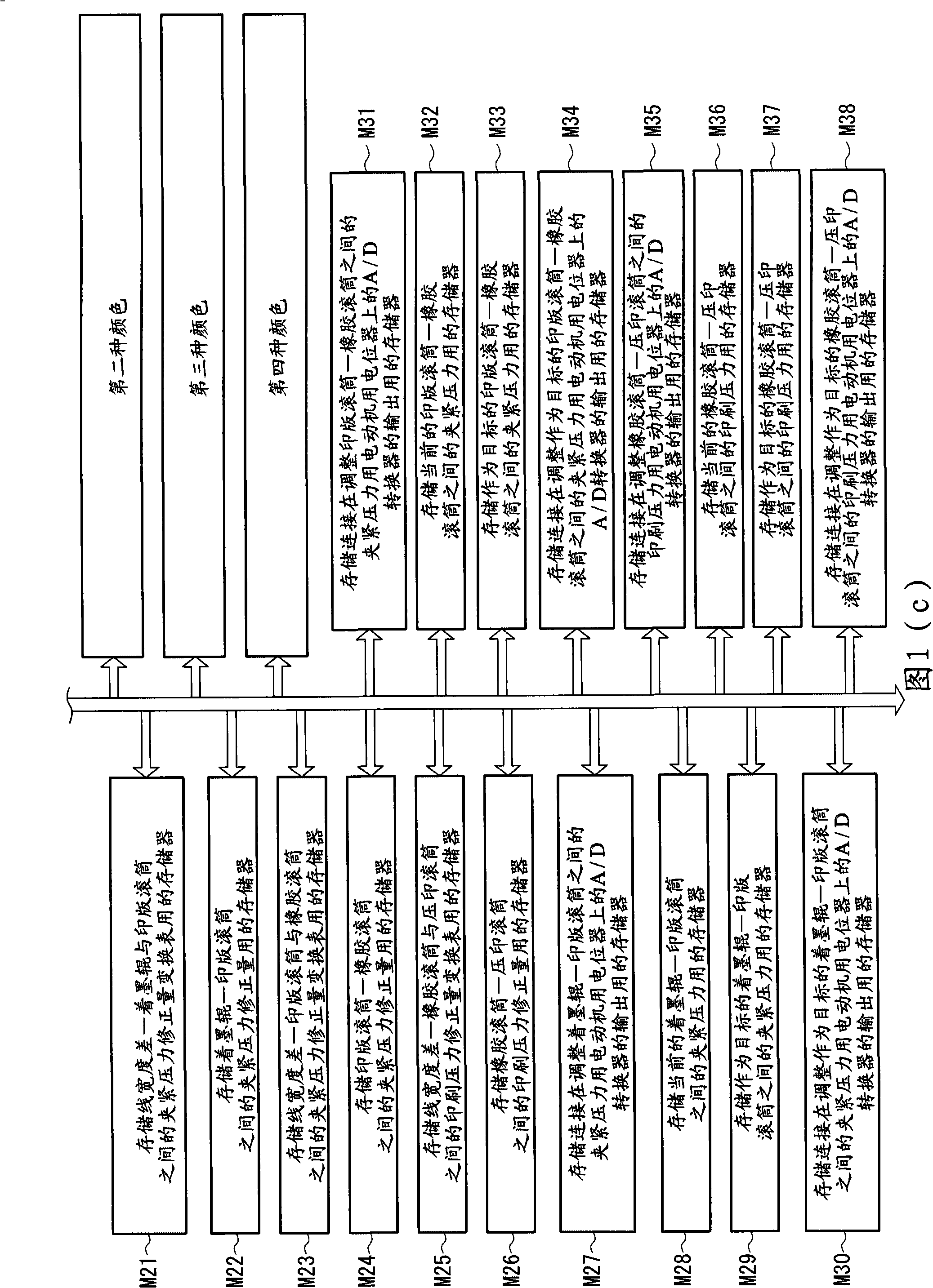
[0184] Fig. 1 (a)~Fig. 1 (c) is the control block diagram of the control device shown in embodiment 1 of the present invention, Figure 2(a) ~ Figure 2(d) is the flow chart of the operation of the control device, Figure 3(a) ~ Figure 3(d) is the flow chart of the operation of the control device, Figure 4(a) ~ Figure 4(d) is the flow chart of the operation of the control device, Figure 5(a) ~ Figure 5(d) It is an action flowchart of the control device, and Fig. 16 is an explanatory diagram of the clamping pressure adjustment mechanism between the ink form roller and the printing plate cylinder, Figure 17 It is an explanatory diagram of the printing pressure adjustment mechanism between the printing plate cylinder and the rubber cylinder, Figure 18 It is an explanatory diagram of the printing pressure adjustment mechanism between the rubber cylinder and the impression cylinder, Figure 19(a) ~ Figure 19(c) It is an explanatory diagram of image judgment.

[0185] First of...

Embodiment 2

[0289] Fig. 6 (a)~Fig. 6 (c) are the control block diagrams of the control device shown in embodiment 2 of the present invention, Figure 7(a) ~ Figure 7(d) is the flow chart of the operation of the control device, Figure 8(a) ~ Figure 8(d) is the flow chart of the operation of the control device, Figure 9(a) ~ Figure 9(d) is the flow chart of the operation of the control device, Figure 10(a) ~ Figure 10(d) It is a flowchart of the operation of the control device.

[0290] In this embodiment, the control device 30 automatically adjusts the clamping pressure between the ink form roller and the printing plate cylinder, the clamping pressure between the printing plate cylinder and the rubber cylinder, and the clamping pressure between the rubber cylinder and the rubber cylinder according to the average width of the printed linear part. The printing pressure between the impression cylinders is replaced by adjusting according to the maximum width of the linear part in Embodime...

Embodiment 3

[0388] Fig. 11 (a) ~ Fig. 11 (c) are the control block diagrams of the control device shown in embodiment 3 of the present invention, Figure 12(a) ~ Figure 12(d) is the flow chart of the operation of the control device, Figure 13(a) ~ Figure 13(d) is the flow chart of the operation of the control device, Figure 14(a) ~ Figure 14(d) is the flow chart of the operation of the control device, Figure 15(a) ~ Figure 15(d) It is a flowchart of the operation of the control device.

[0389] In this embodiment, the control device 30 automatically adjusts the clamping pressure between the ink form roller and the printing plate cylinder, the clamping pressure between the printing plate cylinder and the rubber cylinder, and the clamping pressure between the rubber cylinder and the rubber cylinder according to the area of ​​the linear part (printing part). The printing pressure between the impression cylinders is thus substituted for the adjustment according to the maximum width or th...


PUM


Abstract

Printing quality control method and system for a relief printing press which enable a reduction in a burden of the operator by enabling automatic adjustment of nip pressures and a printing pressure, and a reduction in costs by reducing the number of waste sheets to be produced, the relief printing press including: a first rotor, such as an ink form roller (1), to which ink is supplied; a second rotor, such as a plate cylinder (3), to which the ink is supplied from the first rotor (1); and adjustment means, such as a motor (9), for adjusting, for example, the nip pressure between the first rotor (1) and the second rotor (3). The width of a line portion printed on paper (W) by the relief printing press is measured by using a line-width measuring camera (44), and the adjustment means such as the motor (9) is controlled on the basis of the line portion width obtained by the line-width measuring camera (44).

Description

technical field [0001] The invention relates to a printing quality management method and device for letterpress printing machines Background technique [0002] In the past, in letterpress printing, in the case of the usual offset printing method, due to the clamping pressure (contact pressure) between the ink form roller and the plate cylinder, between the plate cylinder and the rubber cylinder, and between the rubber cylinder and the impression cylinder ) and printing pressure changes, in the case of the direct printing method, due to the clamping pressure (contact pressure) and printing pressure between the ink form roller and the plate cylinder, between the plate cylinder and the impression cylinder and the change of printing pressure, on both sides In the case of the printing method, coupled with the change of the clamping pressure (contact pressure) between the rubber impression cylinder and the rubber cylinder, these will cause the ink to overflow to the periphery of t...

Claims


Application Information

Patent Timeline
Patent Type & Authority Applications(China)
IPC IPC(8): B41F33/00B41F31/02B41F31/32
CPCB41F9/00B41F13/36B41F33/0036B41F33/0072
Inventor 日下明广沼内裕光
Owner KOMORI CORP
Why Eureka
Try Eureka