
Insulation structure of friction specimen holder and apparatus body in current-carrying frictional wear experiment

A sample fixture and wear test technology, which is applied in the testing of machine/structural components, testing of wear resistance, testing of mechanical components, etc., can solve problems such as distortion of test results, loss of test current, and influence on rotation stability

Active Publication Date: 2008-12-24
HENAN UNIV OF SCI & TECH
View PDF0 Cites 7 Cited by
  • Summary
  • Abstract
  • Description
  • Claims
  • Application Information

AI Technical Summary

Problems solved by technology

[0002] In the current-carrying friction and wear test, high-voltage, high-current alternating current or direct current is involved. If there is no insulation protection measure between the test part and the body, not only will the electrical equipment on the body be damaged due to leakage, but the test current will be damaged due to poor insulation. Loss from the body, resulting in distorted test results, which cannot correctly reflect the performance of the test object
For the insulation of high-speed rotating parts and the body, rubber and other traditional soft insulation methods are no longer applicable, which affects the stability of rotation, especially the dynamic balance at high speed

Method used


Image

  • Insulation structure of friction specimen holder and apparatus body in current-carrying frictional wear experiment

Examples


Embodiment Construction

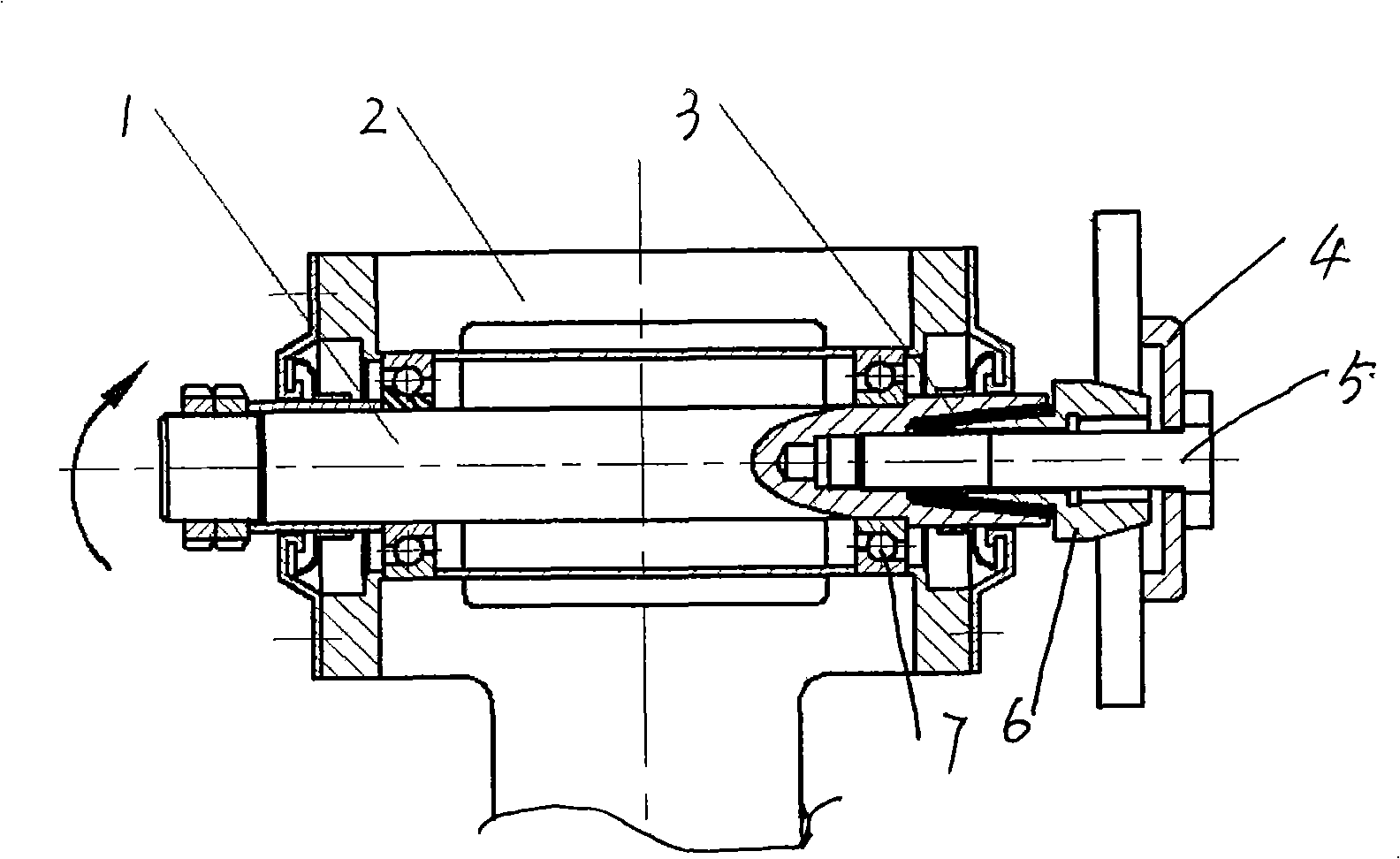
[0010] Such as figure 1 As shown, in the current-carrying friction and wear test equipment of the present invention, the friction sample fixture and the insulation structure of the equipment body, the friction sample fixture is fixedly assembled on the outer end of the transmission shaft, and the transmission shaft is assembled through the rotation of the bearing 7 and the bearing seat 2 On the equipment body, on the transmission shaft of the exposed section inside the fixed assembly position of the friction sample fixture, there is a disconnected surface, which divides the transmission shaft into two sections: the transmission shaft body section 1 and the end section 6, and the left and right transmission sections. The shaft and the shaft are fixed together, and an electrically insulating coating 3 is coated on at least one side of the broken surface. The preferred broken surface is a pair of concave and convex cone structures that cooperate with each other. In this embodimen...


PUM


Abstract

The invention relates to an insulation structure of a friction disc and an equipment body in a current-carrying friction wear testing machine. The friction disc is fixedly assembled at the external end of a transmission shaft; the transmission shaft is rotatablely assembled on the equipment body; a disconnecting surface is arranged on the transmission shaft of the exposed section at the internal side of the fixed assembly position with the friction disc; the disconnecting surface divides the transmission shaft into a left transmission shaft body section, a right transmission shaft body section and an end section; the left transmission shaft section and the right transmission shaft section have the same axis line and are fixed into a whole; electric insulated coating is coated on the disconnecting surface of at least one side. The insulated coating generally has thin thickness, light weight, large hardness, good rigidity and is not easy to deform when bearing the pressure; as the insulation type between the testing part and the machine body of a current-carrying testing machine, the insulation structure of the invention meets the insulation performance requirement at the high speed, improves the rotation precision and ensures the dynamic balance during the high-speed rotation process simultaneously, avoids the infidelity of the test results and correctly reflects the performance of the test objects.

Description

technical field [0001] The invention relates to a current-carrying friction and wear test device, in particular to an insulating structure between a friction sample fixture and a device body in the current-carrying friction and wear test device. Background technique [0002] In the current-carrying friction and wear test, high-voltage, high-current alternating current or direct current is involved. If there is no insulation protection measure between the test part and the body, not only will the electrical equipment on the body be damaged due to leakage, but the test current will be damaged due to poor insulation. The loss from the body causes the test results to be distorted and cannot correctly reflect the performance of the test object. For the insulation of high-speed rotating parts and the body, rubber and other traditional soft insulation methods are no longer suitable, which affects the stability of rotation, especially the dynamic balance at high speeds. Therefore, ...

Claims


Application Information

Patent Timeline
IPC IPC(8): G01N3/02G01N3/56G01M13/00
Inventor 张永振高万振李鹏上官宝李键
Owner HENAN UNIV OF SCI & TECH
Learn More