Device and thread guiding ring for a ring spinning machine or twisting machine

A technology of ring spinning and twisting machines, which is applied to spinning machines, continuous winding spinning machines, textiles and papermaking, etc. It can solve problems such as thread damage, spinning speed not reaching the expected value, and variation. , to achieve the effect of quality improvement

Inactive Publication Date: 2008-12-31
斯图加特德国纺织、纤维研究所
View PDF1 Cites 5 Cited by
  • Summary
  • Abstract
  • Description
  • Claims
  • Application Information

AI Technical Summary

Problems solved by technology

However, the spinning speed that can be increased has not reached the desired value
Since this spinning speed was inc

Method used


Image

  • Device and thread guiding ring for a ring spinning machine or twisting machine
  • Device and thread guiding ring for a ring spinning machine or twisting machine
  • Device and thread guiding ring for a ring spinning machine or twisting machine

Examples


Embodiment Construction

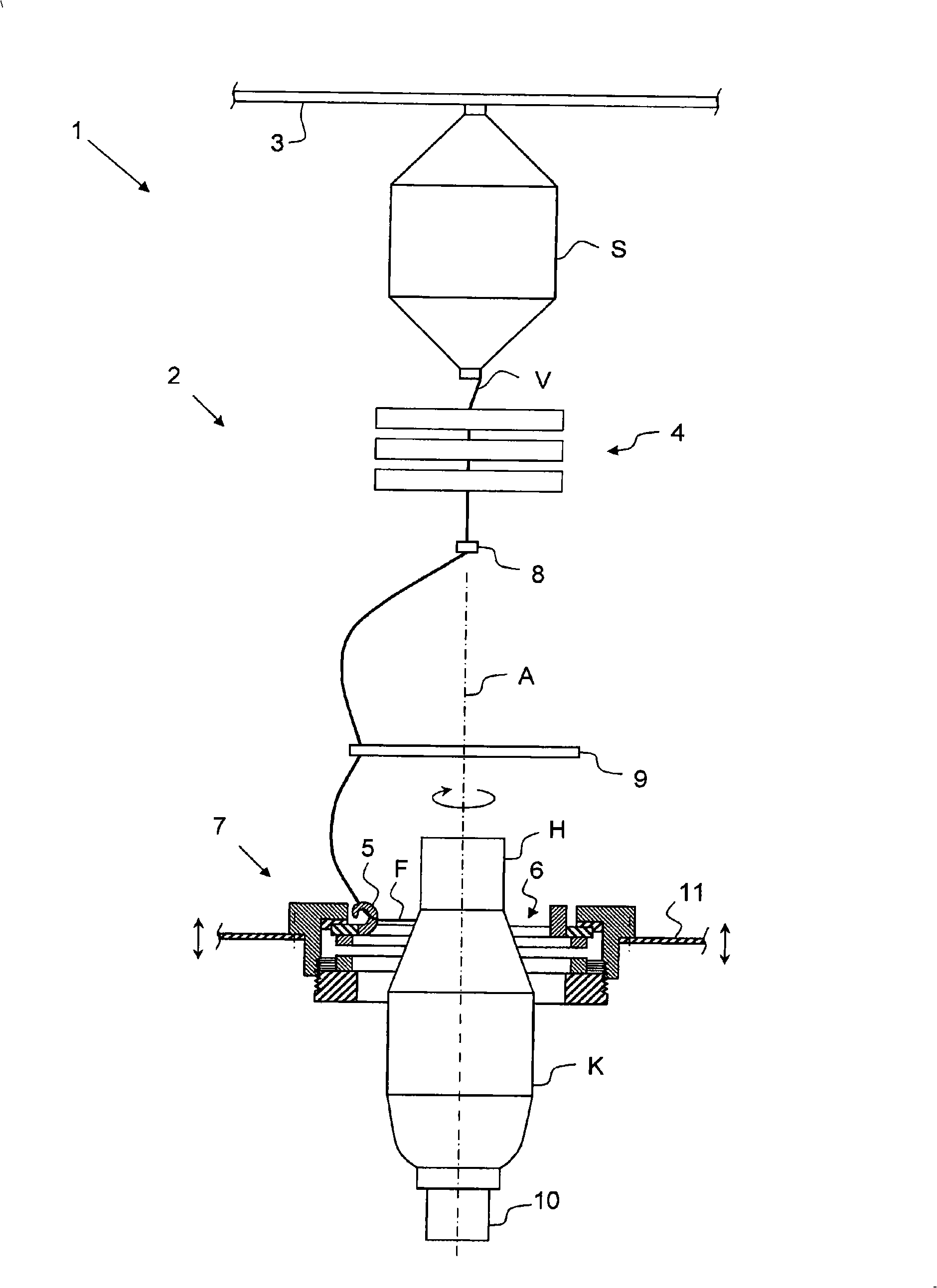
[0072] attached figure 1 A diagrammatic view showing the working position 2 of the ring spinning machine 1 . The ring spinning machine 1 comprises a number of further working units not shown as well as a large number of central devices.

[0073] This working unit 2 comprises a creel 3 on which a bobbin S wound with a thread V is located. The thread V is usually a roving V made of, for example, what is known as a flyer, and carries only a slight protective twist. The thread V is drawn from the bobbin S and passed to a traction system 4, indicated only schematically. Although not visible in this illustration, the traction 4 is positioned at an angle for technical reasons. Its purpose is to pull out the thread V to its final fineness. In order to give strength to the not too thin thread V by twisting the thread V, and to wind the twisted thread F in an appropriate form, a thread guide member 5 is provided, and this is fixed to the thread guide ring spindle 6 . The yarn guide...


PUM


Abstract

The invention relates to a device for ring spinning or twisting machine which is provided with a guide eye (6) the guide parts (5, 5') of which are used for twisting and veer silking (F), and a holding unit (7), the guide eye (6) is arranged on the holding unit (7) and rotates with a given spin axis (A), wherein force generating devices (12, 13; 12', 13'; 28) are used between the axial force (AK) to the guide eye (6), when the device is operated by continuous acting of the force generating devices, a first sliding section (14) formed on the guide eye (6) is bunted on a second sliding section (15)formed on the holding unit (7), thereby providing axial support to the guide eye (6) in that way. The invention also relates to the ring spinning or twisting machine and the guide eye thereof.

Description

technical field [0001] The invention relates to a device for a ring spinning or twisting machine having a yarn guiding ring on which yarn guiding elements for twisting and deflecting the yarn are mounted , and with a holding unit on which the yarn-guiding ring spindle is mounted in such a way that it can rotate around a given axis of rotation. [0002] Furthermore, the invention relates to a yarn-guiding ring spindle for a ring spinning or twisting machine, wherein the ring spinning or twisting machine comprises a yarn-guiding part for twisting or deflecting the yarn, and a ring spinning machine or twister. Background technique [0003] The general task of a ring spinning machine is to impart strength by twisting to the fiber slivers fed thereto and to wind the twisted fiber slivers in a manner suitable for storage, transport and further processing. Fiber slivers fed to ring spinning machines are generally known as rovings that typically only have a weak, protective twist....

Claims


Application Information

Patent Timeline
IPC IPC(8): D01H1/14D01H1/24D01H7/02D01H7/56D01H7/60D01H13/04
CPCD01H7/56D01H7/58D01H7/585
Inventor 于尔根·施奈德乌韦·海特曼S·屈佩尔斯
Owner 斯图加特德国纺织、纤维研究所
Why Eureka
Try Eureka