Digital remote sense geological mapping process and device

A remote sensing and digital technology, applied in the field of digital remote sensing geological surveying and mapping, can solve the problems of limited representation, inability to express the undulating characteristics of the site surface, and inability to obtain the exposed traces of the geological structure surface, so as to reduce manpower and time consumption, eliminate Occupational safety hazards, the effect of excellent rapid mobility

Active Publication Date: 2008-12-31
ZHEJIANG HUADONG ENG DIGITAL TECH CO LTD
View PDF0 Cites 23 Cited by
  • Summary
  • Abstract
  • Description
  • Claims
  • Application Information

AI Technical Summary

Problems solved by technology

[0004] 1. The operation process of the current digital photography recording method is relatively complicated, and a special detection device is required to calibrate the parameters of the digital camera;
[0005] 2. Use the mathematical model to display the three-dimensional image pairs of the venue, and the results can only be used on the two-dimensional plane, without actually obtaining the three-dimensional image model of t

Method used


Image

  • Digital remote sense geological mapping process and device
  • Digital remote sense geological mapping process and device
  • Digital remote sense geological mapping process and device

Examples


Embodiment 1

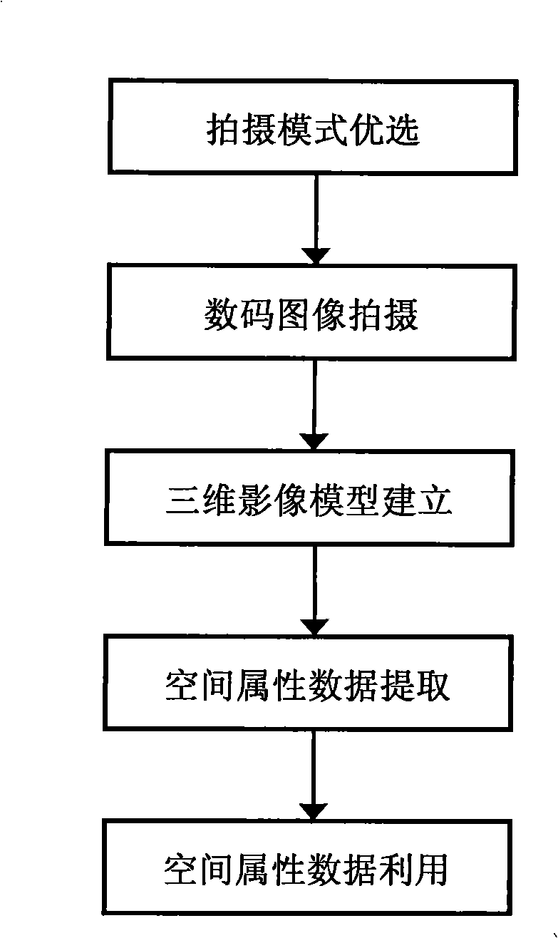
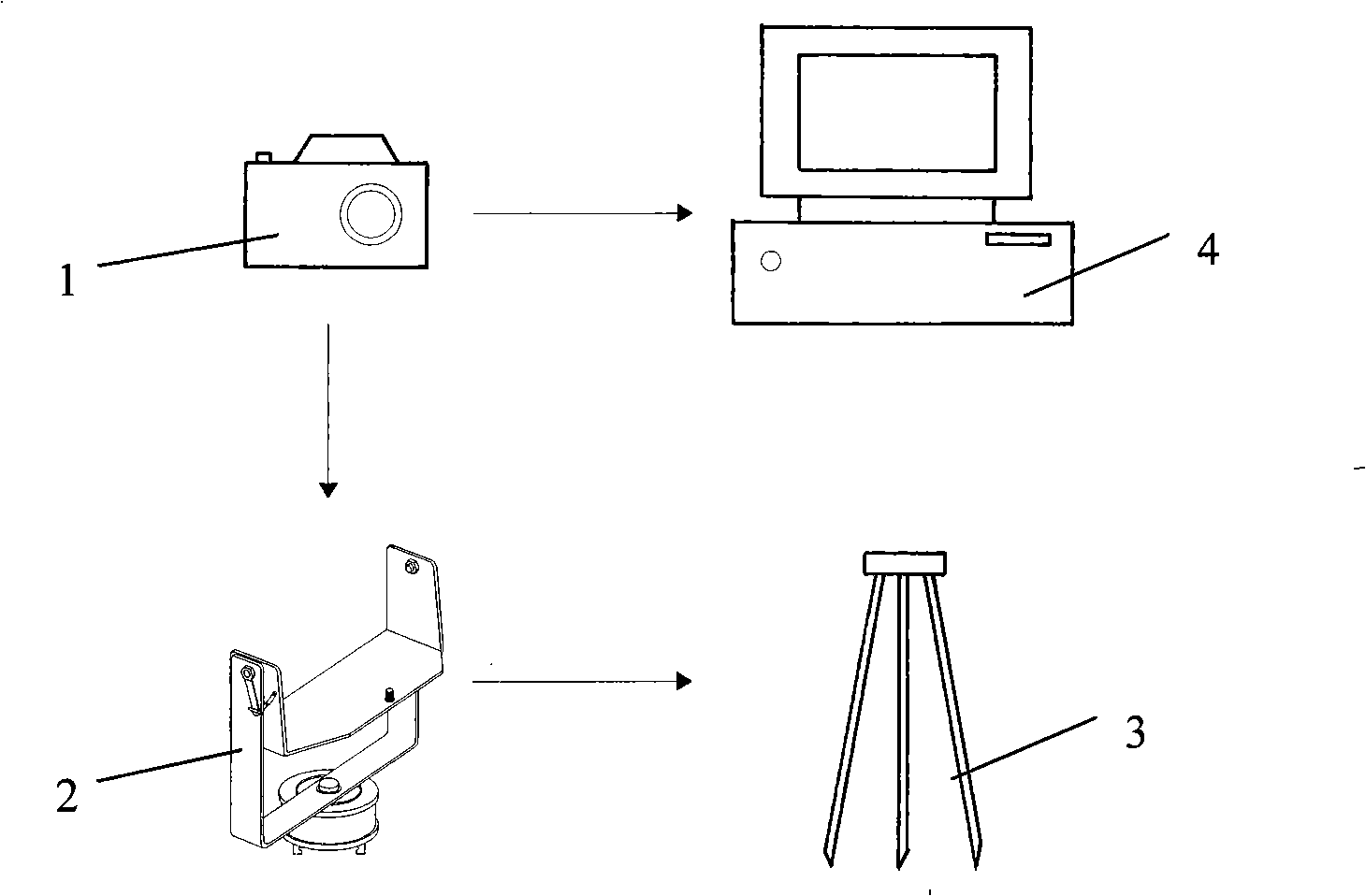
[0037] Example 1, such as Figure 1-3 As shown, the operation method of this example includes the following steps:

[0038] A) The shooting mode in this example is the basic mode, which is suitable for small slopes or excavation of foundation pits. The shooting range is small, and a single photo can present the subject.

[0039] B) digital image capture,

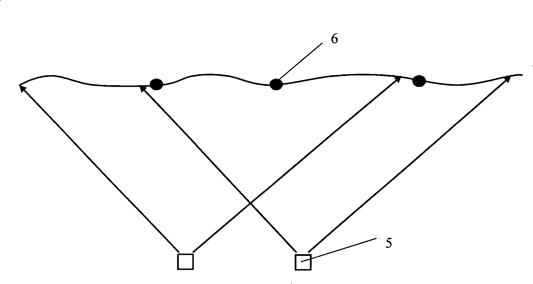
[0040] B1) According to the basic shooting mode selected in step A), it is determined that the digital remote sensing shooting station 5 is two, one left and one right arranged side by side (such as image 3 shown), the principle of shooting site layout is, according to the size of the shooting target site and the distance between the shooting site and the slope, the range of shooting distance is controlled to be 5-250m. The distance in this example is 50m. The ratio range of the distance between them is 1:2-1:10, and all images use the same digital camera with a fixed shooting focal length1,

[0041] B2) set up a tripod ...

Embodiment 2

[0048] Example 2, such as figure 1 , figure 2 , Figure 4 As shown, the operation method of this example includes the following steps:

[0049] A) The shooting mode in this example is extended mode, which is suitable for large slopes or foundation pits. Generally, it is used because the size of the shooting site exceeds the viewing angle range of a single photo.

[0050] B) digital image capture,

[0051] B1) According to the extended shooting mode selected in step A), it is determined that the digital remote sensing shooting site 5 is two, arranged side by side (such as Figure 4 As shown), the principle to determine the location of the shooting site is to control the range of shooting distance to 5-250m according to the size of the shooting object and the distance between the shooting site and the slope. The distance in this example is 100m. The ratio range of the distance between the object stations is 1:2-1:10, and all images use the same digital camera with a fixed f...

Embodiment 3

[0057] Example 3, such as figure 1 , figure 2 , Figure 5 As shown, the operation method of this example includes the following steps:

[0058] A) This example is suitable for underground caves or mountain valleys. Since the shooting range is narrow and long, the shooting mode is strip mode.

[0059] B) digital image capture,

[0060] B1) According to the shooting mode selected in step A), a row or nearly parallel rows of shooting sites are arranged at equal intervals. In this example, two rows are arranged (such as Figure 5 Shown), a plurality of shooting stations 5 are arranged on each row, and all images use the same digital camera 1 with a fixed shooting focal length,

[0061] B2) set up a tripod 3 at the determined photographing site position, the tripod can be a special wooden or metal tripod for general measurement, the digital camera 1 of this example selects the Canon EOS-5D digital camera from Canon Corporation of Japan, and the digital camera 1 is fixed on On...


PUM


Abstract

The invention relates to a method and a device for digital remote sensing geology mapping, the technical problem to be solved by the invention is to provide a method for digital remote sensing geology mapping based on the techniques, such as digital photogrammetry, digital image processing, and static three-dimensional image establishment and engineering geology analysis, etc. The technical proposal to solve the problem is: A) the preference of shooting modes, one corresponding mode of three shooting modes which are a basic mode, an extended mode and a strip-map mode, is selected according to three site conditions which are a high and steep slope, foundation pit excavation and an underground cavern; B) the shooting of digital images; C) the establishment of a three-dimensional image model; D) the extraction of spatial attribute data; and E) the utilization of the spatial attribute data. The method and the device of the invention can be applied to the geology mapping (logging) of the high and steep (rock) slope, the foundation pit excavation and the underground cavern in various constructions, such as water conservancy, hydroelectric power, transportation and mines, etc.

Description

technical field [0001] The invention relates to a method and device for digital remote sensing geological surveying and mapping. It is mainly used in geological surveying and mapping (recording) of high and steep (rock) slopes, excavation foundation pits and underground caverns in various projects such as water conservancy, hydropower, transportation, and mining. Background technique [0002] Engineering geological surveying and mapping refers to the use of methods such as data collection, survey visits, geological surveys, and remote sensing interpretation to find out the engineering geological elements of the site and draw corresponding engineering geological maps. As an indispensable and extremely important content in engineering geological work, engineering geological surveying and mapping (catalogue) plays an important role in eliminating geological hidden dangers, optimizing design, choosing reasonable construction methods, guiding the safe operation of the project and...

Claims


Application Information

Patent Timeline
IPC IPC(8): G01C11/00G01C11/04
Inventor 单治钢王国光贾海波
Owner ZHEJIANG HUADONG ENG DIGITAL TECH CO LTD
Why Eureka
Try Eureka