

Imaging device
A technology of camera devices and camera components, which is applied in printing devices, projection devices, image communication, etc., can solve problems such as continuous vibration of camera units, inability to perform blur correction, increased mechanical vibration, etc., and achieve high-precision effects
- Summary
- Abstract
- Description
- Claims
- Application Information
AI Technical Summary
Problems solved by technology
Method used
Image

Examples
no. 1 Embodiment approach
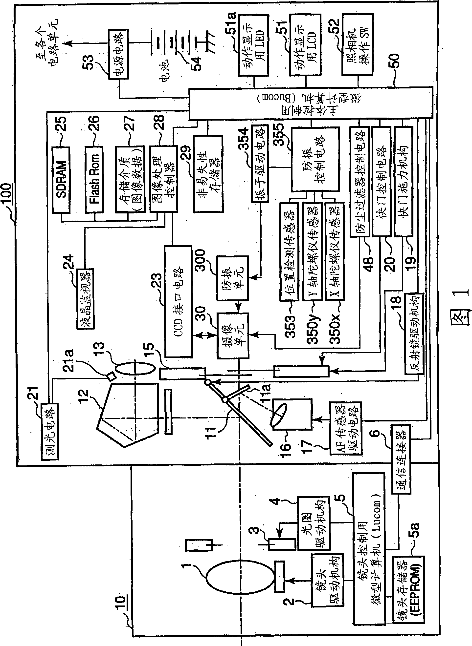
[0054] First, a first embodiment of the present invention will be described. 1 is a block diagram schematically showing a main electrical system configuration of a digital camera (hereinafter referred to as a camera) according to a first embodiment of the present invention. The camera of this embodiment is configured as a camera system including a body unit 100 as a camera body and a lens unit 10 as an interchangeable lens.
[0055] The lens unit 10 is configured to be detachable via a not-shown lens mount provided on the front surface of the main body unit 100 . The control of the lens unit 10 is performed by a lens control microcomputer (microcomputer) (hereinafter referred to as "Lucom") 5 that it has. The main body unit 100 is controlled by a main body control microcomputer (hereinafter referred to as “Bucom”) 50 . These Lucom 5 and Bucom 50 are connected via a communication connector 6 so as to be communicable in a state where the lens unit 10 is mounted on the main bod...
no. 2 Embodiment approach
[0135] Next, a second embodiment of the present invention will be described. The second embodiment shows a second method for determining the stability of a blur correction device. When the blur correction device is in an unstable state, the amplitude of the target drive position obtained from the outputs of the X-axis gyroscope 350x and the Y-axis gyroscope 350y and the focal length of the photographic lens 1 is as described above. Figure 14 As shown in (a), it gradually increases in the frequency band of mechanical vibration.
[0136] In the second embodiment, if Figure 19As shown, the positive and negative thresholds (Thresh_2) are set for the differential value of the target driving position (the amount of change in the target driving position per predetermined period is substantially the same). When the number of times the differential value of the target drive position reaches the positive and negative differential thresholds reaches a predetermined number of times (S...
no. 3 Embodiment approach
[0144] Next, a third embodiment of the present invention will be described. The third embodiment discloses a third method for determining the stability of a blur correction device. When the blur correction device is in an unstable state, the amplitude of the position detection value of the position detection sensor 353 is as described above Figure 14 As shown in (a), it gradually increases in the frequency band of mechanical vibration.
[0145] In the third embodiment, if Figure 22 As shown, the positive and negative thresholds (Thresh_3) are set for the differential value of the position detection value obtained from the output of the position detection sensor 353 (the amount of change per predetermined period is substantially the same). When the number of times the differential value of the position detection value reaches the positive and negative differential thresholds reaches a predetermined number of times (StbTime_3), it is determined that the blur correction devic...
PUM
 Abstract
Description
Claims
Application Information