Surface-mounted contraposition apparatus and method thereof

A surface mount and alignment device technology, applied in the direction of electrical components, electrical components, etc., can solve problems such as manpower and time, alignment errors, and affecting the quality of surface mounting of electronic components, so as to improve efficiency and improve The effect of precision

Inactive Publication Date: 2008-12-31
AVARY HLDG (SHENZHEN) CO LTD +1
View PDF0 Cites 28 Cited by
  • Summary
  • Abstract
  • Description
  • Claims
  • Application Information

AI Technical Summary

Problems solved by technology

[0004] However, the image sensor device of the vision alignment system usually has a field of view of only 50mm×50mm
Due to the limitation of the field of view, the image sensor device usually can only directly obtain the entire image coordinates of electronic components of small size (size less than 50mm×50mm), so it can only realize automatic alignment of small-sized electronic components piece
When the size of the electronic components to be mounted is large, such as a connector part (Connector) with a size of 62mm×6mm, since this size has exceeded the field of view of the image sensor device of the vision alignment system, it cannot be accurately placed. Obtain the entire image coordinates of electronic components, making it impossible to achieve accurate automatic alignment and placement
Therefore, at present, the alignment placement of large-sized electronic components usually needs to be done manually, which not only consumes more manpower and time, but also easily causes artificial alignment errors during the alignment placement process, thus affecting the waiting time. Surface Mount Quality of Mounted Electronic Components

Method used


Image

  • Surface-mounted contraposition apparatus and method thereof
  • Surface-mounted contraposition apparatus and method thereof
  • Surface-mounted contraposition apparatus and method thereof

Examples


Embodiment Construction

[0015] The surface mount alignment device and its alignment method provided by the technical solution will be further described below in conjunction with the accompanying drawings and embodiments.

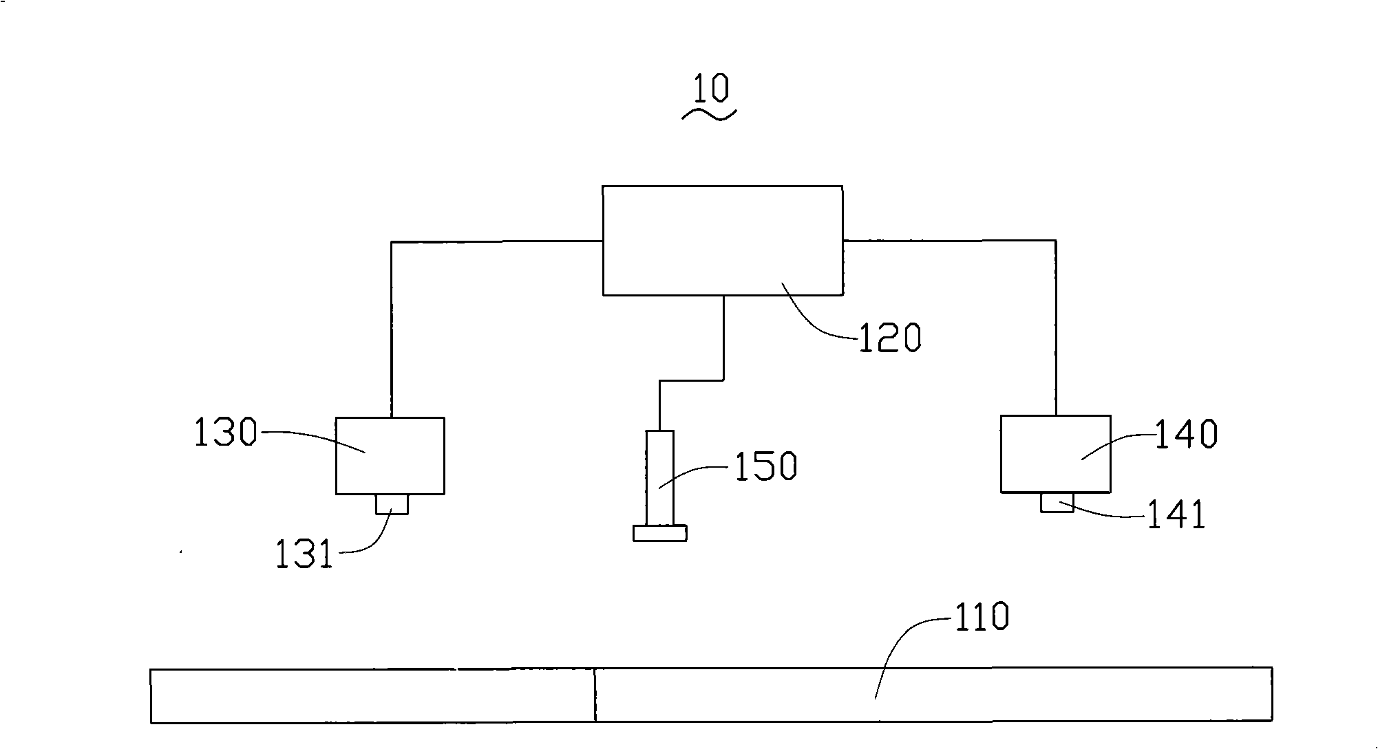
[0016] see figure 1 , the first surface mount alignment device 10 provided by the embodiment of the technical solution. The surface mount alignment device 100 includes a workbench 110 , a central control processing device 120 , a first image sensing device 130 , a second image sensing device 140 and a pick-and-place device 150 .

[0017] The workbench 110 is used for placing objects to be sensed, such as electronic components and printed circuit boards to be mounted. The worktable 110 is set opposite to the first image sensing device 130, the second image sensing device 140 and the pick-and-place device 150, so that the first image sensing device 130 and the second image sensing device 140 can be viewed from the workbench 110. above the workbench 110 to perform image sensing on t...


PUM


Abstract

The invention relates to a surface mounting contraposition method, comprising: using a first image sensing device to sense a profile image of an electronic device, and using a central control processing device to obtain geometry center coordinate of the electronic device; using a second image sensing device to sense a profile image of a pad of a printed circuit board, and using the central control processing device to obtain geometry center coordinate of the pad; moving a pickup patch device to pick up the electronic device to perform contraposition patch, thereby realizing correct automatic contraposition patch of the electronic device in large size, effectively advancing efficiency and accuracy of the surface mounting contraposition patch of the electronic device in large size. The invention also relates to a surface mounting contraposition device.

Description

technical field [0001] The invention relates to surface mount technology, in particular to a surface mount alignment device and an alignment method thereof. Background technique [0002] Surface Mount Technology (SMT) has been widely used in the assembly of electronic components and printed circuit boards due to its high reliability and ease of automation. [0003] At present, electronic components can use automatic placement equipment to realize automatic alignment and placement of electronic components and pads of printed circuit boards, so as to achieve accurate surface mounting. See literature Capson, D.W.; Tsang, R.M.C, Automatic visual measurement of surface-mount device placement, Robotics and Automation, IEEE Transactions on, 1990, 6(1), 44-52. Automatic placement equipment usually has a visual alignment system. During the automatic surface mounting process of electronic components and printed circuit boards, the image sensor device of the visual alignment system, s...

Claims


Application Information

Patent Timeline
Patent Type & Authority Applications(China)
IPC IPC(8): H05K13/02H05K13/08
CPCH05K13/0812Y10T29/4913Y10T29/49133Y10T29/49131Y10T29/53174
Inventor 朱银奎王峰晖毕庆鸿
Owner AVARY HLDG (SHENZHEN) CO LTD
Why Eureka
Try Eureka