Magnetic control drum apparatus of bike riding-balance simulator

A simulation device and bicycle technology, which is applied to sports accessories, muscle training equipment, gymnastics equipment, etc., can solve the problem that the distance between the rollers cannot be adjusted, it cannot meet the different needs of cyclists' riding resistance, and the size of the rotating resistance of the roller cannot be adjusted, etc. question

Inactive Publication Date: 2009-01-07
FUZHOU SUNUR ELECTRONICS TECH
View PDF1 Cites 15 Cited by
  • Summary
  • Abstract
  • Description
  • Claims
  • Application Information

AI Technical Summary

Problems solved by technology

[0002] The patent number is 200720173213.X, and the invention name is a utility model patent for a bicycle riding balance simulation device. Although the bicycle riding balance simulation device disclosed by it solves the balance simulation control problem of a bicycle riding in situ, the rotation resistance...

Method used


Image

  • Magnetic control drum apparatus of bike riding-balance simulator
  • Magnetic control drum apparatus of bike riding-balance simulator
  • Magnetic control drum apparatus of bike riding-balance simulator

Examples


Embodiment Construction

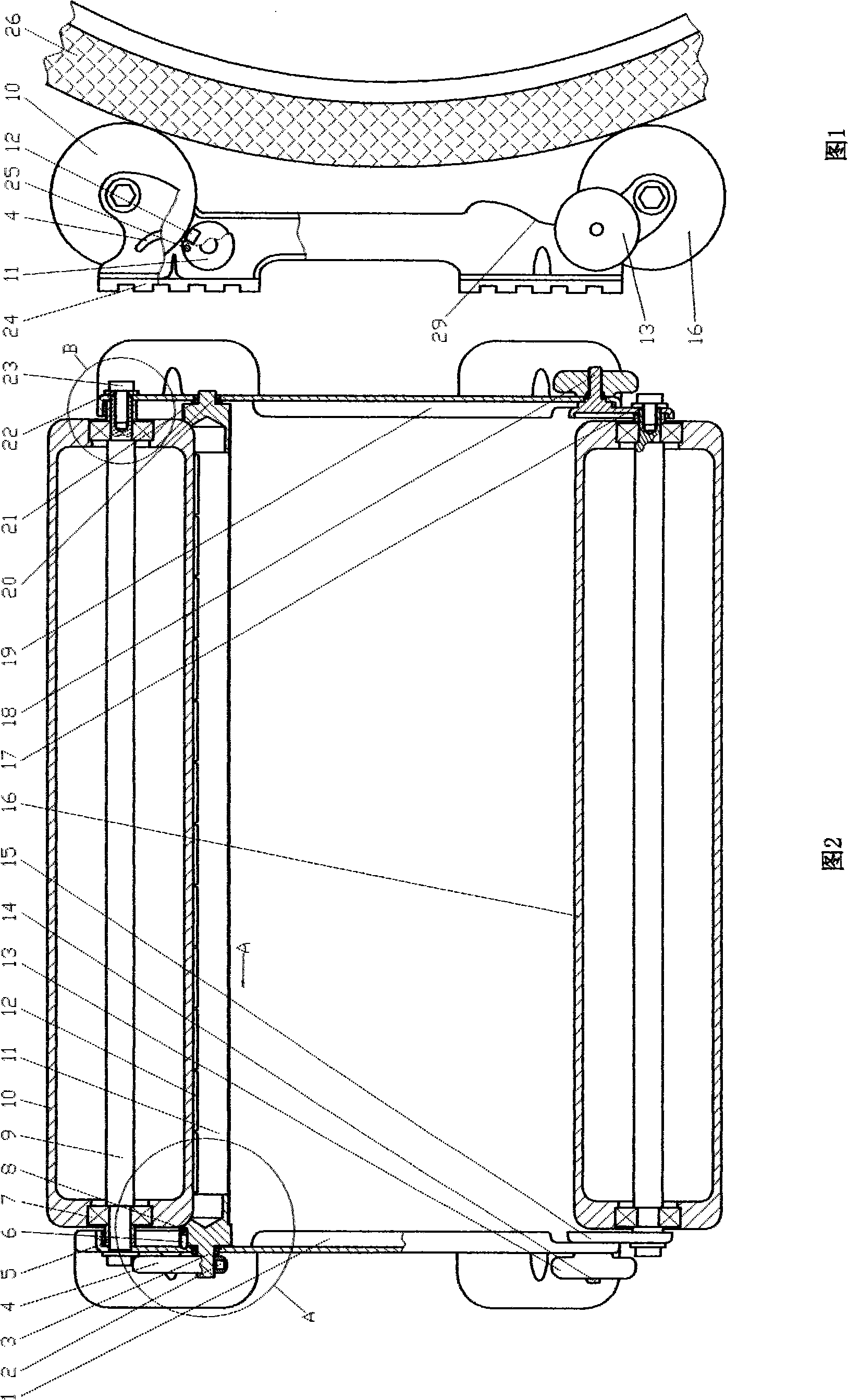
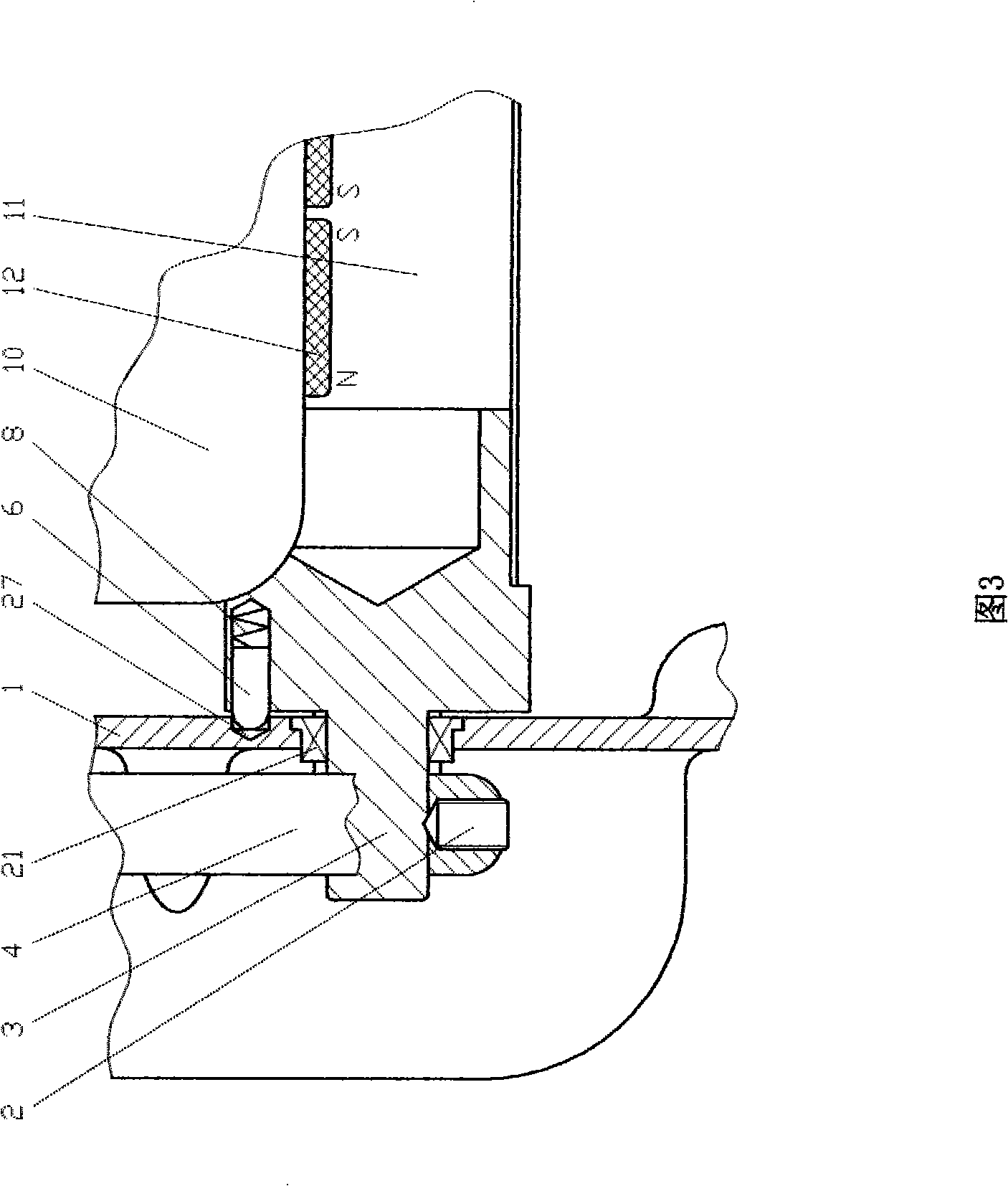
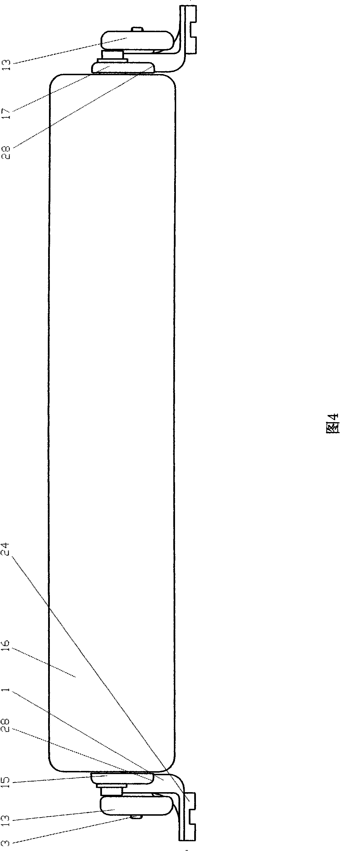
[0025] Referring to Fig. 1 and Fig. 2, the magnetron drum device of the present invention includes a front drum 10, a rear drum 16 and a magnetron 11 parallel to the axes of the two drums and positioned at the rear and lower side of the front drum; Both ends are provided with bearing holes, and roller bearings 7 are housed in the holes, which are connected with the holes at the front of the left and right brackets 1 and 19 through the roller shaft 9, the roller bushing 5, the shaft end pressing piece 22, and the shaft end screw 23. The two ends of the rear drum 16 are also provided with bearing holes and built-in drum bearings 7, through the drum shaft 9, the drum bushing 5, the shaft end pressing piece 22, the shaft end screw 23, and the left and right support members 15 , 17 on the hole connection; the bottom of the left and right supports 15,17 are respectively hingedly installed on the rear of the left and right supports 1,19 by the left and right support rotary shafts 14,1...


PUM


Abstract

The invention provides a magnetron roller device of a bicycle riding equilibrium simulating device. The magnetron roller device comprises a front roller made of metal, a rear roller, and a magnetron made of non-magnetic metal, is in parallel with the two rollers and is arranged at a rear lower part of the front roller. The bearing holes are arranged at two ends of the front roller, are provided with a roller bearing therein, and are connected to the holes at the front part of a left bracket and a right bracket via the roller spindles, the shaft sleeves and the fastener. The two ends of the rear roller are connected to the holes on a left support member and a right member via the same structure, the left support member and the right support member are connected to the holes at the rear part of the left bracket and the right bracket via a left support gyro shaft and a right support gyro shaft, and an elastic wheel screwed on to the gyro shafts. The magnetron is connected to the front parts of the left bracket and the right bracket via a left end shaft and a right end shaft at two ends and a magnetron bearing on the end shafts. A row of small magnetic strips are arranged in a position in parallel with a tubular axis and close to the front roller. A regulating handle is fixed on the outer side of the left end shaft of the magnetron via a small stud. A pin hole is arranged on the left end surface of the magnetron, and a small pressure spring and a half-round movable pin in the pin hole are correspondent to the spacing blind holes on the inner sides of the left bracket and the right bracket. The notches are arranged on the inner sides at the rear part of the left bracket and the right bracket for spacing the left support member and the right support member. The antiskid gaskets are arranged at the bottoms of the left bracket and the right bracket.

Description

technical field [0001] The invention relates to a magnetic control roller device of a bicycle training platform, in particular to a magnetic control roller device of a bicycle riding balance simulation device. Background technique [0002] The patent number is 200720173213.X, and the invention name is a utility model patent for a bicycle riding balance simulation device. Although the bicycle riding balance simulation device disclosed by it solves the balance simulation control problem of a bicycle riding in situ, the rotation resistance of the drum is limited. The size cannot be adjusted, and the distance between the front and rear rollers cannot be adjusted, so: [0003] 1. It cannot meet the different needs of riders for riding resistance; [0004] 2. The adaptability of the roller to contact with the rear wheels of bicycles with different outer diameters is poor. Contents of the invention [0005] The object of the present invention is to provide a magnetic control ro...

Claims


Application Information

Patent Timeline
IPC IPC(8): A63B21/005A63B69/16
Inventor 徐峰
Owner FUZHOU SUNUR ELECTRONICS TECH
Why Eureka
Try Eureka