Method for operating a warp knitting machine and warp knitting machine

An operating method and technology of warp knitting machines, applied in the field of warp knitting machines, can solve problems such as increased noise emission, production capacity limitation, etc., and achieve the effect of increasing mechanical load

Inactive Publication Date: 2009-01-07
KARL MAYER TEXTILMASCHFAB GMBH
View PDF1 Cites 3 Cited by
  • Summary
  • Abstract
  • Description
  • Claims
  • Application Information

AI Technical Summary

Problems solved by technology

In addition, noise emissions will increase
The possible product

Method used


Image

  • Method for operating a warp knitting machine and warp knitting machine

Examples


Embodiment Construction

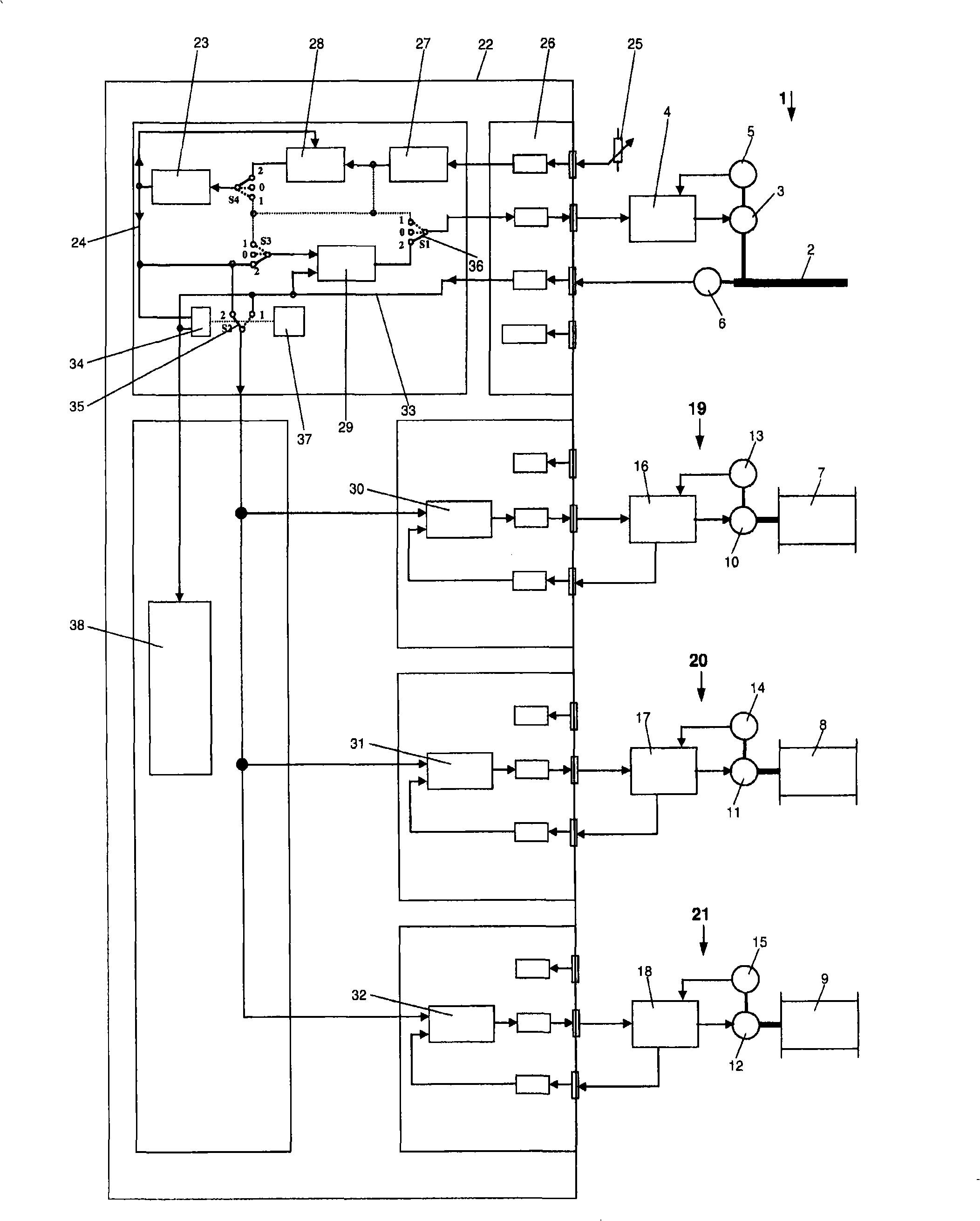
[0029]A warp knitting machine 1 shown only in general terms has a spindle 2 which is driven by a spindle drive 3 . The spindle drive 3 is controlled by a drive amplifier 4 . The drive amplifier 4 is in turn connected to an angle encoder 5 which constantly determines the rotational angle position of the spindle drive 3 .

[0030] The spindle 2 is likewise connected to an angle encoder 6 which continuously determines the rotational angular position of the spindle.

[0031] The warp knitting machine 1 also has a number of follower drives 19-21 for controlling the movement of the pattern bars or beams, for example. Three such follower drives 19-21 are shown here by way of example, the respectively driven elements are simply referred to as "follower shafts" 7-9. Each follower shaft 7-9 is driven by a motor 10-12. Each motor 10-12 is connected to an angle encoder 13-15, which in turn transmits the current angular position of the motor 10-12 to the drive amplifier 16-18. The driv...


PUM


Abstract

The invention provides a warp knitting machine (1) and its operation method. The warp knitting machine comprises a main axle (2) driven by main axle driving device (3), at least a following drive device (19-21) and a controller for controlling following drive device according to capstan. In addition controller (22) comprises a capstan generator (23) for forming virtual capstan. The invention is to provide a high yield warp knitting machine.

Description

technical field [0001] The invention relates to a method of operating a warp knitting machine with a main shaft driven by a main shaft drive, wherein at least one follower drive is controlled as a function of the capstan shaft. [0002] Furthermore, the invention relates to a warp knitting machine with a main shaft driven by a main shaft drive, at least one follower drive and a control device for controlling the follower drive as a function of the capstan. Background technique [0003] Such a method and a warp knitting machine are known from DE 42 157 98 C2. The spindle is driven by the spindle drive. Usually different elements of the knitting machine are driven by the main shaft of the warp knitting machine, such as the needle bed and the bar swing bars. The other elements of the knitting machine are driven by follower drives. For example the bars, in particular the pattern bars, are driven by a follower drive. The warp beam of the knitting machine is also driven by a f...

Claims


Application Information

Patent Timeline
IPC IPC(8): G05B19/18D04B27/00
CPCD04B27/08D04B27/26D04B27/00
Inventor M·洛伦茨J·柯克纳G·克劳斯M·奥特
Owner KARL MAYER TEXTILMASCHFAB GMBH
Why Eureka
Try Eureka