Refrigerant compressor

A refrigerant and compressor housing technology, applied in household refrigeration devices, mechanical equipment, machines/engines, etc., can solve the problems of non-exclusion, susceptible to corrosion, warping of collection containers, etc., to ensure accurate fit, adaptation, corrosion, etc. Simple problem, cost saving effect

Active Publication Date: 2009-01-07
ACC AUSTRIA GMBH
View PDF4 Cites 5 Cited by
  • Summary
  • Abstract
  • Description
  • Claims
  • Application Information

AI Technical Summary

Problems solved by technology

[0010] In general, it can thus be said that steel collection vessels do have higher evaporative performance and give a higher compressor cooling coefficient (COP) compared to plastic collection vessels, but due to their susceptibility to corrosion, steel collection vessels are more demanding manufacturing and / or maintenance effort
In contrast, with plastic collection containers, no anti-corrosion measures are required, however said air gaps due to the connection to the compressor housing adversely affect the evaporative performance and the cooling coefficient (COP) of the compressor
[0011] An evaporation device for melt water is known from FR 7423927, which has a plastic collection container that can be placed on the compressor housing and adapted to the shape of the housing, wherein by making the bottom part relatively small in wall thickness compared to the remaining wall parts , prevents thermal insulation of the collection vessel, however, the air gap formed between the compressor housing and the collection vessel is also not excluded or satisfactorily minimized
Although this evaporator uses a thermoplastic material, which is adapted to the compressor housing at high operating temperatures, in the case of softening of this material, undesired warping of the collection container and even the formation of air bubbles can occur, because of the The thermodynamic process of softening does not proceed in a monitorable and actively controlled manner

Method used


Image

  • Refrigerant compressor
  • Refrigerant compressor
  • Refrigerant compressor

Examples


Embodiment Construction

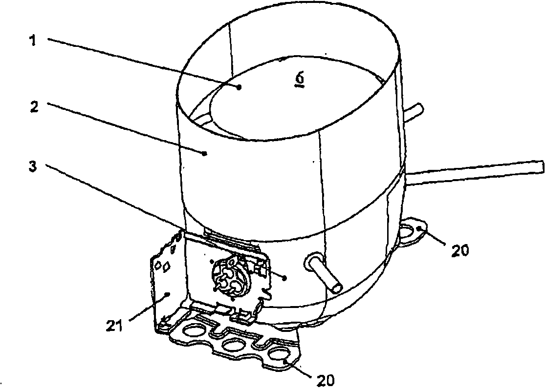
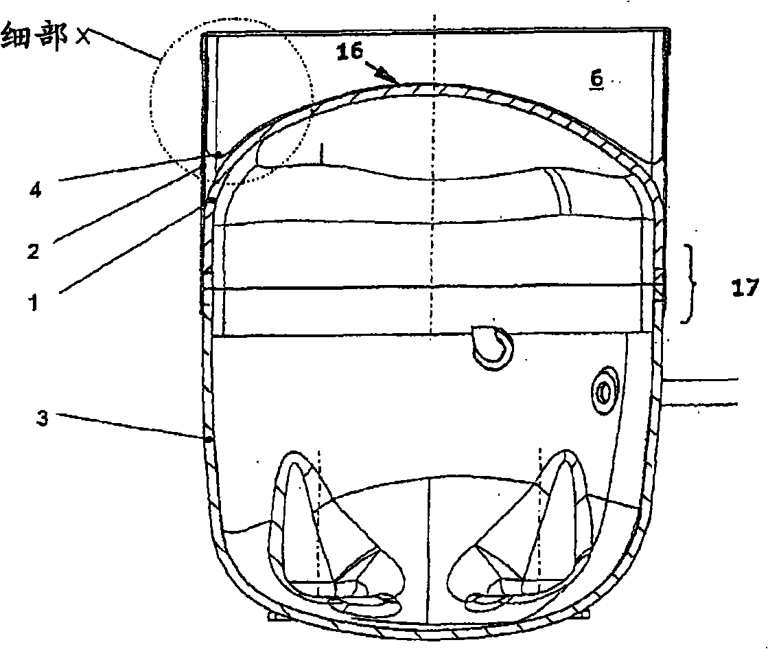
[0056] figure 1 Showing a small refrigerant compressor according to the invention, the compressor housing comprises a base part 3 and a cover part 1 which together define a hermetic chamber. A piston-cylinder arrangement (not shown) is located in this hermetic chamber closed by a compressor housing in a manner known per se, which is connected to a suction line and a pressure line through which refrigerant flows into the piston-cylinder arrangement , The pressure pipe leads the refrigerant compressed in the piston-cylinder device from the inside of the compressor housing.

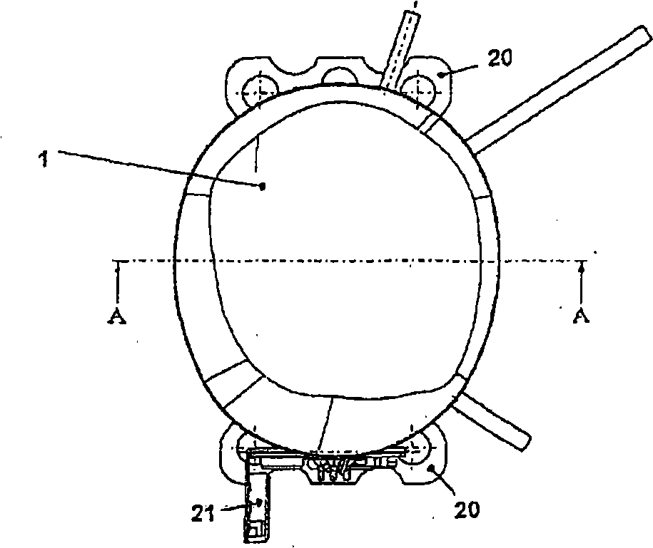
[0057] The small refrigerant compressor itself is fastened to the compact refrigerator and is responsible for dissipating the heat from the cooling chamber of the compact refrigerator. Also shown are a mounting flange 20 and an adapter flange 21 with which the small refrigerant compressor is fastened to the small refrigerator and through which the small refrigerant compressor is powered.

[0058] As illus...


PUM


Abstract

The aim of the invention is to create a receptacle (4) which is used for evaporating condensed liquid on a small coolant compressor, allows the heat generated by the small coolant compressor to be utilized in an optimal way, and is easy and inexpensive to produce and mount on the compressor housing. Said aim is achieved by embodying the receptacle (4) as a plastic part that is deep-drawn in a receiving device (6) directly on the compressor housing. The plastic part perfectly matches the shape of the receiving device (6) such that the air gap that is usually formed between the compressor housing and the receptacle (4) can be eliminated altogether or reduced to a minimum. A holding element (2) that is arranged on the outer circumference of the cover part (1) ensures optimum support for the receptacle (4), thus dispensing with the need for expensive anti-corrosive measures while the evaporator power and the coefficient of performance (COP) of the small coolant compressor are optimized.

Description

technical field [0001] The invention relates to a compressor housing with a cover and a base according to the preamble of claim 1, which housing is hermetically sealed for a small refrigerant compressor, on which a collecting container made of plastic is arranged to For evaporation of condensed liquid, the container is held in a receptacle formed on the compressor housing; the invention also relates to a collector made of plastic for the manufacture and installation on the compressor housing according to the preamble of claim 19 method of the container. Background technique [0002] This type of small refrigerant compressor is primarily used in the domestic sector and is usually located at the back of the refrigerator. The purpose is to compress the refrigerant circulating in the cooling system and transport it further, whereby heat is removed from the interior of the refrigerator, dissipated into the surrounding environment, thus cooling the refrigerator compartment or she...

Claims


Application Information

Patent Timeline
Patent Type & Authority Applications(China)
IPC IPC(8): F25D21/14
CPCF25D21/14F25D2321/1442F25D2321/145F25D2321/1411F04B39/121
Inventor 福尔克尔·施蒂布勒
Owner ACC AUSTRIA GMBH
Why Eureka
Try Eureka